parametric paint shelf for clarke cwr50 metal tool board
10 Jun 2017

(thingiverse / customiser)
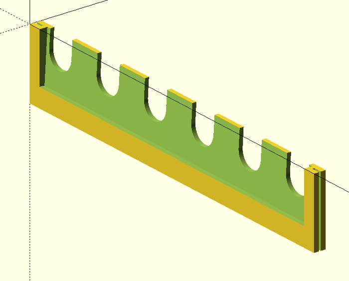
Simple 3D scad model for the Clarke CWR50 tool board - to hold small paint tubes. The shelves are angled back a little, so the tubes won't fall off. With some minor modifications I guess it would be useful for small tools etc as well.
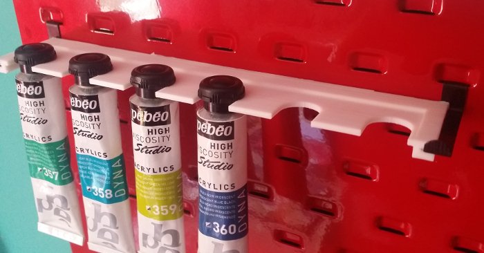
The design is fully parametric, and you can specify the number of hook perforations wide you want the shelf to be (num), the size (paint_slot_width) and spacing (paint_slot_spacing) between the centres of the paint slots. The scad code will then squeeze in as many as possible.
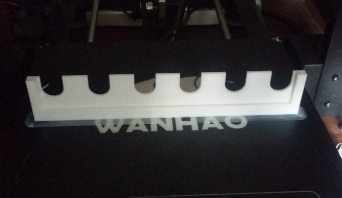
Ours were printed to be six hook perforations wide; that's widest I can print on my Wanhao i3, and conveniently the longest rows on the tool board were 18 wide, so I could print three per row. The paint tubes also happen to be almost the same width as the perforations too, so there's six slots.
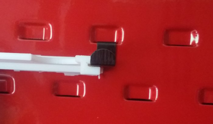
The hooks that came with the board slot into the ends of the shelves. They only go in half way though, so the hook can be shared between two adjacent shelves.
Scad code:
$fn = 0 + 0;
$fs = 0.1 + 0; // HQ cylinders
$fa = 4 + 0; // HQ spheres/hulls

// number of hooks wide
num = 6; // [1:18]

// width of the slots
paint_slot_width = 14.5;
// space between the slot centres
paint_slot_spacing = 31;

// space between the hook centres
hook_spacing = 31;

shelf_height = 6;
shelf_thickness = 2;
shelf_width = hook_spacing * num;

hook_width = 8.5;
hook_depth = 34.5;
hook_height = 1;

usable_shelf_width = shelf_width-(hook_width*1.5) -1;
usable_num_slots = round(usable_shelf_width/paint_slot_spacing);

num_slots = usable_num_slots;
shelf_centre = (shelf_width/2);
holes_width = (paint_slot_spacing * (num_slots-1)) ;
holes_centre = (shelf_centre - (holes_width/2));

module paint_slot(){
    hull(){
        cylinder(r=paint_slot_width/2, h=30);
            translate([0, hook_depth/4, 0])
                cylinder(r=paint_slot_width/2, h=30);
    }
}

rotate([-90, 0, 0]){
//rotate([0, 0, 0]){

    difference(){
        cube([shelf_width, hook_depth, shelf_height]);

        //paint slots
        translate([holes_centre, 0, -10]){
            for(i=[0:num_slots-1]){
                translate([paint_slot_spacing*i, 0, 0])
                    paint_slot();
            }
        }

        //tilt neg
        rotate([-3.3, 0, 0]){
            translate([((hook_width*1.5)/2), 0-(1/2)-10, shelf_height])
                cube([shelf_width-(hook_width*1.5), hook_depth+1, shelf_height]);
            translate([((hook_width*1.5)/2), 0-(1/2)-10, 0-shelf_thickness ])
                cube([shelf_width-(hook_width*1.5), hook_depth+1, shelf_height]);
        }

        translate([0-(hook_width/2), 0-1, (shelf_height-hook_height)/2])
            cube([hook_width, hook_depth+(1*2), hook_height]);

        translate([shelf_width-(hook_width/2), 0-1, (shelf_height-hook_height)/2])
            cube([hook_width, hook_depth+(1*2), hook_height]);
    }
}
3d printing|scad|
picam mod for rspb camera feeder housing
12 May 2017
(thingiverse link)
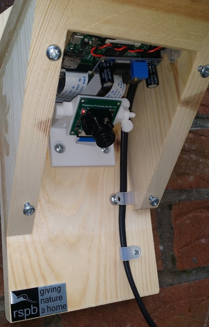
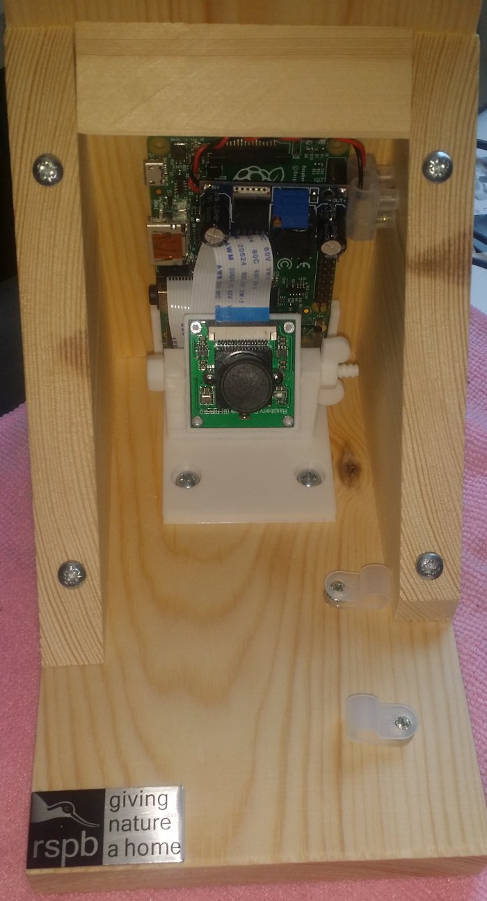
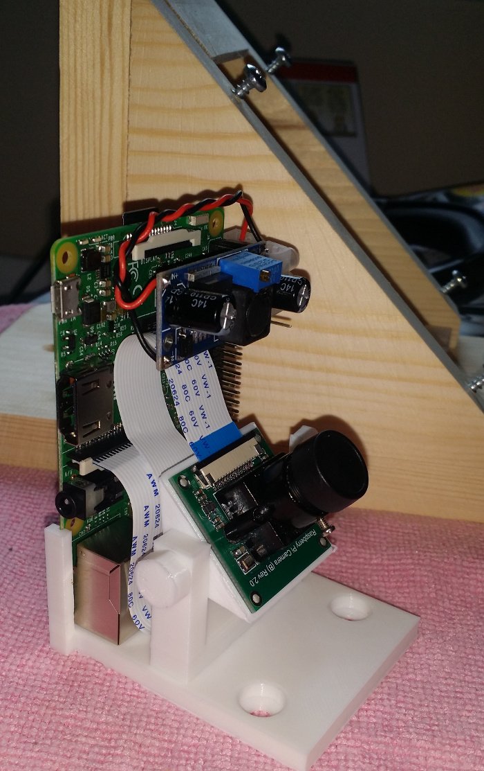
This is a drop-in raspberry pi camera mount for the RSPB's camera feeder housing. It uses the same screw and screw holes the supplied bracket uses, no modifications are required to the housing. The angle of the 'head' is adjustable, using a bolt and nut from Mike Mattala's nut job.
The camera board is attached using the screws used to hold the lense mount; they are simply removed, then fed through the back of the head, before going through the board and into the lense mount. The camera board I'm using
is the Waveshare OV5647, although the scad file is easily adjusted to suit most boards. (The official rpi foundation camera boards might need a pair of small nuts and bolts as they come with a small, glued down, mobile phone-type lense mount.)
The raspberry pi is slotted into two arms at the rear. Power is provided via a LM2596 based buck converter board, sat on a +5v and a ground on the 40 pin header.
Scad code for the head - adjust 'lens_screw_space' as required:
$fn = 0;
$fs = 0.1; // HQ cylinders
$fa = 4; // HQ spheres/hulls

cam_w = 35;
cam_d = 35;

lens_screw_space = 20;
//lens_screw_space = 18;

plate_w = cam_w;
plate_d = cam_d;
plate_h = 0.5;

screw_hole = 2;
screw_head = 4;
screw_flange = 1;
screw_h = 10 + 0.1;

lid_w = 35;
lid_d = 10;
lid_h = 1;
lid_z = 10;

tilthole = 5;

module screw(){
    cylinder(r=screw_head/2, h=screw_h);
    translate([0, 0, 0-2])
        cylinder(r=screw_hole/2, h=screw_h);
}

module screws(){
    translate([cam_w/2, cam_d/2, screw_flange]){
        translate([lens_screw_space/2, 0, 0])
            screw();

        translate([0-(lens_screw_space/2), 0, 0])
            screw();
    }
}

module tilt(){
    rotate([0, 90, 0])
        translate([0-(lid_z/2), plate_d/2, 0-(((cam_w*1.2)-plate_w)/2)])
            cylinder(r=tilthole/2, h=cam_w*1.2);
}

module body(){
    hull(){
        cube([plate_w, plate_d, plate_h]);

        translate([(cam_w-lid_w)/2, (cam_d-lid_d)/2, lid_z-1])
            cube([lid_w, lid_d, lid_h]);
    }
}

difference(){
    body();

    tilt();
    screws();
}
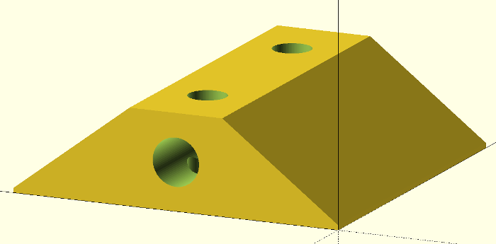
Scad code for the base - if you find that the screw holes in the feeder are off centre (mine were), you can adjust 'h_offset' to shift the bracket left or right:
$fn = 0;
$fs = 0.1; // HQ cylinders
$fa = 4; // HQ spheres/hulls

block_w = 35;
block_h = 25;

slot_base_extra_d = 26;

base_w = 55;
//base_d = 40;
base_d = 40 + 26;
base_h = 5;

bracket_h = 36;
bracket_d = 10;
bracket_w = block_w + (2 * 6.5);

tilthole = 5;
tilthole_l = base_w;

mount_hole_space = 40;
mount_hole_from_edge = (base_w - mount_hole_space ) /2;
mount_hole_screw_head = 10;
mount_hole_screw = 5;
mount_hole_from_end = 15;

h_offset = 0; //offet the bracket, if the holes are off centre

slot_w = 56.5;
slot_d = 1.5;
slot_h = 85;

holder_w = slot_w + 4;
holder_d = slot_d + 4;
holder_h = 26;

bottom_h = 5;

chopout_w = slot_w - 2;
chopout_d = holder_d * 2;
chopout_h = holder_h + 0.1;

module pislot(){
    difference(){
        cube([holder_w, holder_d, holder_h+bottom_h]);

        translate([(holder_w-slot_w)/2, (holder_d-slot_d)/2, bottom_h])
            cube([slot_w, slot_d, slot_h]);

        translate([(holder_w-chopout_w)/2, (holder_d-chopout_d)/2, bottom_h])
            cube([chopout_w, chopout_d, chopout_h]);
    }
}

module mount_hole(){
    translate([0, 0, 1.5])
        cylinder(h=100, r=mount_hole_screw_head/2);
    translate([0, 0, -1])
        cylinder(h=100, r=mount_hole_screw/2);
}

module mount_holes(){
    translate([0, base_d-mount_hole_from_end, 0]){
        translate([mount_hole_from_edge, 0, 0])
            mount_hole();

        translate([base_w-mount_hole_from_edge, 0, 0])
            mount_hole();
    }
}

module base(){
    difference(){
        cube([base_w, base_d, base_h]);
        mount_holes();
    }
}

module tilt_bracket(){
    difference(){
        translate([((base_w-bracket_w)/2)+h_offset, 0, 0])
            cube([bracket_w, bracket_d, bracket_h]);

        translate([((base_w-block_w)/2)+h_offset, 0-(block_w/4), bracket_h-block_h+0.1])
            cube([block_w, block_w, block_h]);

        rotate([0, 90, 0])
            translate([0-bracket_h+tilthole, bracket_d/2, 0])
                cylinder(r=tilthole/2, h=tilthole_l);
    }
}

translate([(holder_w-base_w)/2, 0, 0]){
    base();
    translate([0, slot_base_extra_d, 0])
        tilt_bracket();
}
pislot();
3d printing|scad|
wanhao small spoolholder
27 Nov 2016
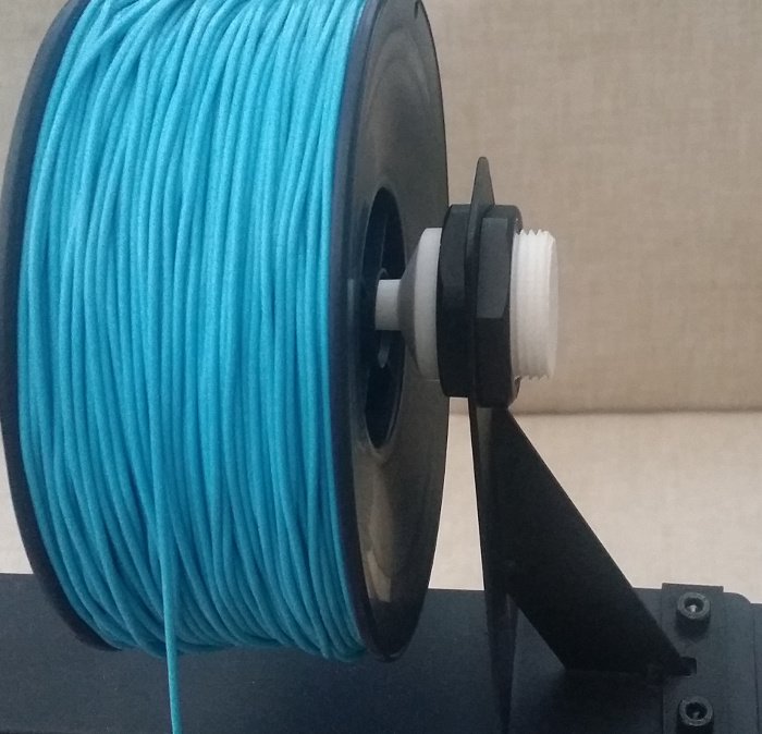
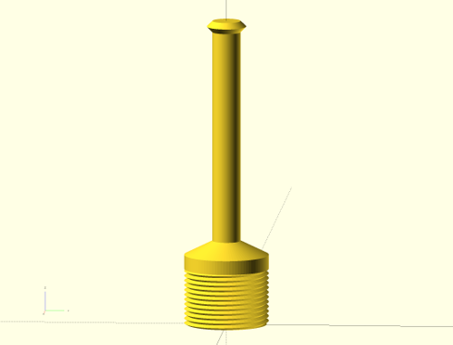
I needed a smaller spool holder for a 500 gram spool of filament, so I've hacked together this. The hard work generating the screw thread is done by aubenc's polyScrewThread.scad.
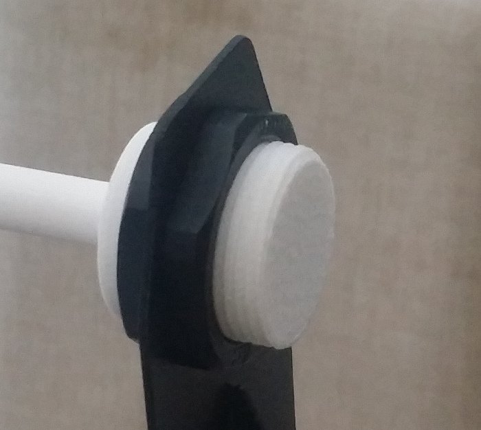
It uses the same M30 nuts the stock Wanhao spool holder uses.
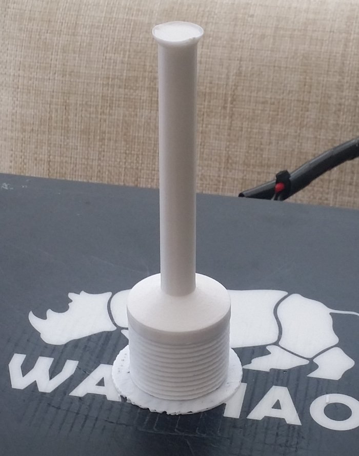
Printed vertically, 40% in-fill seems to be strong enough.
$fn = 0;
$fs = 0.1; // HQ cylinders
$fa = 4; // HQ spheres/hulls

include <polyScrewThread.scad>

PI=3.141592;

fat_diam = 30;
fat_r = fat_diam/2;
stop_length = 5;
screw_length = 20;

poke_length = 80;
poke_diam = 10;
poke_r = poke_diam/2;
poke_end = 2;
poke_overhang = 2;

screw_thread(fat_diam, 1.7, 30, screw_length, PI/2, 0);

translate([0, 0, screw_length])
    cylinder(stop_length, fat_r, fat_r);

translate([0, 0, screw_length+stop_length]){
    cylinder(poke_length, poke_r, poke_r);

    cylinder(stop_length, fat_r, poke_r);
}

translate([0, 0, screw_length+stop_length+poke_length]){
    cylinder(poke_end, poke_r, poke_r+poke_overhang);

    translate([0, 0, poke_end])
        cylinder(poke_end, poke_r+poke_overhang, poke_r);
}
wanhao duplicator i3|scad|
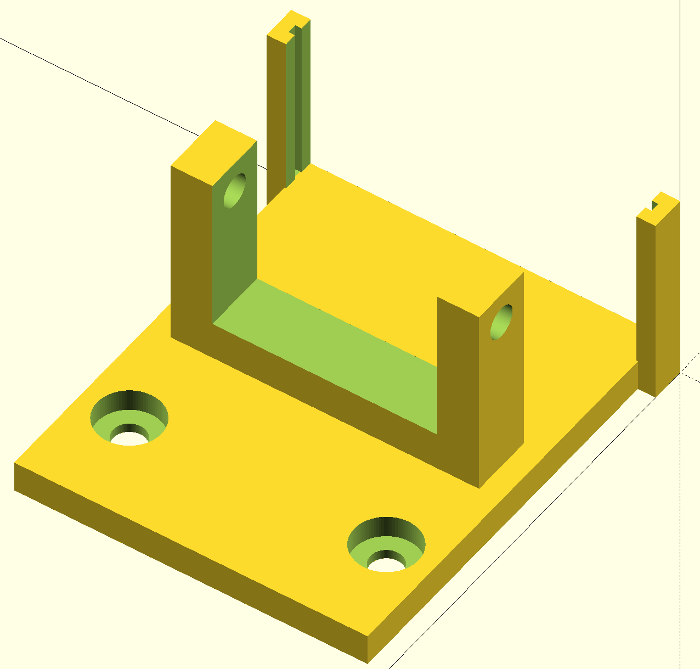
wanhao aluminum extruder adaptor
30 Oct 2016
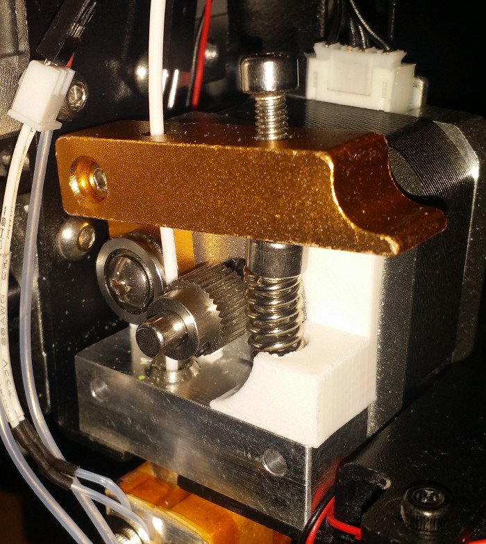
After a fair amount of printing, the extruder in our cheap Wanhao Duplicator i3 started to fail. The plastic arm and spring were no longer applying enough pressure on the filament and was unable to grip it properly. I tried printing an adjustable arm but I had some issues with the grooved bearing not turning freely, which was causing the motor to slip.
While browsing through extruder parts on Amazon, I noticed this cheap aluminum extruder. I wasn't properly paying attention when I ordered it and I didn't notice that the cooling block on the printer would be conflicting with the new extruder. Unfortunately the block on the new extruder has a threaded hole, rather than the grub screw used on the Wanhao and so I couldn't easily change the block over either.
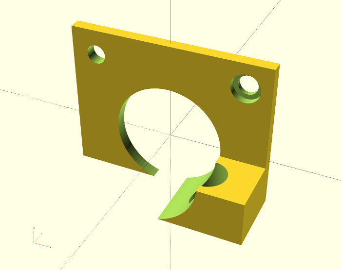
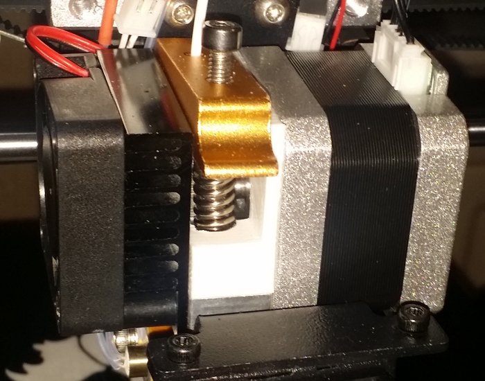
After a bit of messing in openscad, I've created a simple adaptor - it's real job is just to stop the spring from sliding out.
The new arm - along with the higher quality grooved bearing that came with it - works well and print quality has improved noticeably.
$fn = 0;
$fs = 0.1; // HQ cylinders
$fa = 4; // HQ spheres/hulls


block_width = 15 - 0.5;
block_height = 10;

arm_width = 12;

plate_depth = 42;
plate_height = 42;
plate_width = block_width - arm_width;

rotor_hole = 23;

motor_screw_hole = 3.5 + 0.5;
motor_screw_head_depth = 2 - 0.5;
motor_screw_head = 6;
motor_screw_hole_spacing = 31.5;

spring_holder_offset = 9;
spring_holder_offset2 = 1.5;
spring_holder_height = 10;
spring_holder_depth = spring_holder_offset * 2;
spring_holder_bottom = 2;

spring = 7.5 + 0.5;
spring_length = 19;

difference(){
    union(){
        cube([plate_depth, plate_width, plate_height], center=true);

        translate([0+(plate_depth/2)-(spring_holder_offset), 0-(block_width/2)+(plate_width/2), 0-(plate_height/2)+(block_height)+(spring_holder_height/2)]){

            difference(){
                cube([spring_holder_depth, block_width, spring_holder_height], center=true);
                translate([0, 0-spring_holder_offset2, 0-(spring_holder_height/2)+spring_holder_bottom])
                    rotate([0, -5, 0])
                        cylinder(spring_length, spring/2, spring/2);
            }
        }
    }
    rotate([90, 0, 0]){
        cylinder(100, rotor_hole/2, rotor_hole/2, center=true);

        translate([motor_screw_hole_spacing/2, motor_screw_hole_spacing/2, 0]){
            cylinder(100, motor_screw_hole/2, motor_screw_hole/2, center=true);

            translate([ 0, 0, 0+ (plate_width/2) + (10/2) - motor_screw_head_depth ])
                cylinder(10, motor_screw_head/2, motor_screw_head/2, center=true);
        }

        translate([0-(motor_screw_hole_spacing/2), motor_screw_hole_spacing/2, 0])
            cylinder(100, motor_screw_hole/2, motor_screw_hole/2, center=true);

    }

    translate([0, 0, 0-(plate_height/2)])
        cube([plate_depth*2, 50, block_height*2], center=true);
}
wanhao duplicator i3|scad|
battletanks reverse engineering
30 Oct 2016
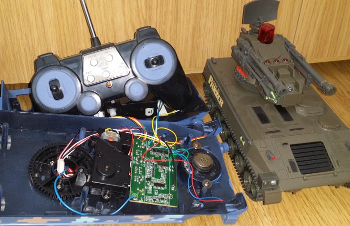
We've been watching the repeats of the old robot wars for a while now and with the start of the new series we thought we'd quite like to have some small scale wars at home. While I'd like to build a pair of robots from scratch, this would likely take more time than I have available. So I took my fingers to amazon to look for a couple of RC vehicles that had more than just the driving controls, so the extra functions could be utilised to drive weapons/flippers etc.
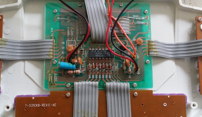
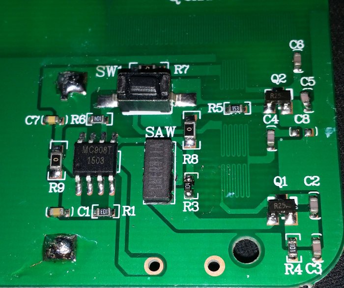
After a bit of searching I found a double pack of "battle tanks". They have the expected forwards, backwards and rotate left/right drive controls, but also have rotating turrets and some other buttons (fire, fx1, fx2, demo and on/off). Out-of-the-box the game is that each tank has three lives and has to shoot the other - they have a IR LED and receiver mounted on the turret (you can see them on the Panzer). The tanks also produce a bunch of sound effects to accompany the game.
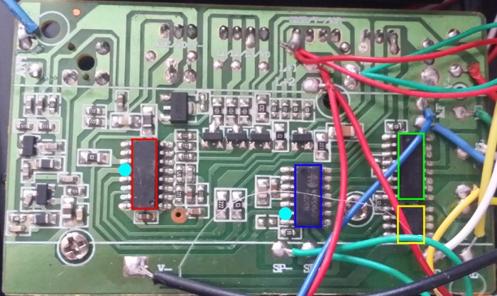
Taking a look at the board inside one of the tanks, you can see that it's primarily made up of four ICs: the first one implements the radio receiver and the majority of the game (red); it's connected directly to the IR and RF electronics, as well as the three 'lives' LEDs on top of the turret. The red chip is connected to the second IC (blue) by a single data line (the two cyan pins on the red/blue chips). The blue chip generates both the sound effects (the speaker is directly connected to it - green wires: SP-/SP+) and the signals required to drive the two H-bridge ICs that control the tracks (green) and turret motors (yellow).
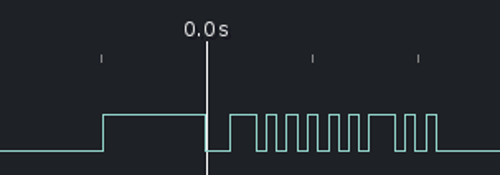
The data line is an one-way path from the red IC to the blue IC. Data is sent nine bits at a time, with a ~970us high/~240us low indicating the start (the zero line in the image above is at the high/low transition). The bits themselves are encoded as a either ~100us or ~240us pulses, with a ~100us gap between them. Assuming 100us is one and 240us is zero, the above example decodes as "100000100".
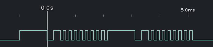
Some button presses translate to multiple bytes (above is the demo button). The red IC also tracks a certain amount of state: the fx2 button will cycle through three different set of bytes on each button press. Here's most of the mappings:
shoulderR   110000000
shoulderL   101000000

left        100010000
right       100001000
forward     100000100
backwards   100000010

demo        100000000 100000000
shoot+sound 100000000 000000010
fx1         000001100 100000000
byebye      000010010
on          000000100
off         000010010 100000000
fx2,1       000011010 100000000
fx2,2       000000110 100000000 000000110
fx2,3       000000010 100000000
From here it should be possible to remove the blue chip and then patch in a microcontroller. It should be able to detect the controls and then either drive the existing H-bridges, or additional servos, sensors etc. Removing the IR receiver and tying it's line should effectively disable the built-in game.
That's the plan anyway...
reverse engineering|battletanks|
mediatek mt6261 rom dumping via the vibration motor
7 Feb 2016
When I was pulling apart my u8plus smartwatch, I noted that there were five unlabelled pads, and that these were likely jtag:
Although I had reasonable results with jtagenum, nothing I tried worked with a real adaptor. I turned to google and rediscovered bunnie/xob's work on fernvale. Xob specifically mentions problems with jtag:
"In theory it has JTAG, which should let us attach a debugger and break the execution flow of the CPU. However, we never got it working, and it's unclear what steps must be taken, or even which set of pins to use."
Making the assumption that if bunnie/xob couldn't get the jtag working, I was unlikely to stumble on the required magic. Instead I pulled xob's repo to see what it would do with the mt6261. It was able to connect and extract a bunch of information:
Waiting for serial port to connect: .......
Setting serial port parameters... Ok
Initiating communication... Ok
Getting hardware version... 0xcb01
Getting chip ID... 0x6261
Getting boot config (low)... 0x0000
Getting boot config (high)... 0x0000
Getting hardware subcode... 0x8000
Getting hardware version (again)... 0xcb01
Getting chip firmware version... 0x0001
Getting security version... v 5
Enabling security (?!)... Ok
Reading ME... 00000000 ad 3f 07 fa 5e 5d 0b ad  10 71 b2 02 3d 5b e5 a3  |.?..^]...q..=[..|
Disabling WDT... Ok
Reading RTC Baseband Power Up (0xa0710000)... 0x0002
Reading RTC Power Key 1 (0xa0710050)... 0xa357
Reading RTC Power Key 2 (0xa0710054)... 0x67d2
Setting seconds... Ok
Disabling alarm IRQs... Ok
Disabling RTC IRQ interval... Ok
Enabling transfers from core to RTC... Ok
Reading RTC Baseband Power Up (0xa0710000)... 0x0002
Getting security configuration... None.
Getting PSRAM mapping... 0x0000
Disabling PSRAM -> ROM remapping... Ok
Checking PSRAM mapping... 0x0002
Checking on PSRAM mapping again... 0x0002
Updating PSRAM mapping again for some reason... Ok
Reading some fuses... 0x00000000
Enabling UART... 0x0000
This looked promising but it was hanging before it could attempt to upload the first stage. A lucky guess (based on reading *somewhere* that 6261 had less SRAM) at hacking the load address and the stack address let it continue though to:
Loading Fernly USB loader... checksum matches 0x1ec6 Ok
Executing Ferly USB loader... Ok
Waiting for Fernly USB loader banner...
At this point, it seems that we might have code running on the cpu; the watch was unresponsive until I pulled the USB - I was hoping I had at least crashed it..
The fernly usb loader is able to read/write memory pretty trivially, so I used it's functions to dump the 4MB of onboard flash (at 0x0). I also attempted to 'spray' all over the area where the uart blocks are on the 6260; with the bus pirate connected to the hardware uart, I thought I'd at least see something random spit out - no luck.
Having a dump of the flash to analyse is useful, but - from reading though the fernly information - a dump of the rom (at 0xfff00000) is where a lot of the hardware detail is hiding. I didn't expect that to be a problem, I expected the usb loader to just dump it out for me; instead it hung, turns out that area is protected from usb reads.
After quite a while of searching for something even remotely looking like a memory map for the 6261, so I could use the uart to dump the rom, I came across this post by jimparis. He'd been through the same process, and also hadn't been able to find the uarts. What he had found though was the address of the vibration motor; his code buzzed the motor on my watch too. Jim also says "So I'm sure that code is running now. What's next? Try to find and dump the internal ROM via the motor? :/"
When I read that, I vaguely remembered reading about how the original ipod rom was dumped and thought that I could do something similar with the vibrator motor. My set up is much simplier than the ipod - I de-soldered the motor and after a quick examination with the scope, I patched the line into an adruino.
The assembler for the mt6261-test image was modified to loop through a memory range, reading in a 32 bit value, and then generating a pulse for each bit. I'm lazy - I chose a short 'on' (1x call to delay()) for zero, a long 'on' (2x calls to delay(), so double the length), using 'off' to represent the gap between bits; e.g:
1 0 1 0 0 1 = off, long, off, short, off, long, off, short, off, short, off, long, off
The main assembler loop was debugged using qemu-arm+gdb (the image can be used as a qemu flash image) before attempting to upload to the real device. On the arduino side, a pin was monitored and the length of the pulses was tracked. If the pulse was over a certain threshold then a '1' is output, otherwise a '0'. To validate the method before dumping the unknown rom, I dumped the first part of the flash - this was compared with the data dumped using the usb loader and after a few tweaks they were bit perfect. A small bit of throwaway python was hacked together to reassemble the bits into a file:
s = """
10110000000000000000000001010111
01111111111111111111111101010111
01111111111111111111111101010111
01111111111111111111111101010111
01111111111111111111111101010111
01111111111111111111111101010111
01111111111111111111111101010111
01111111111111111111111101010111
...
00000000000000000000000000001110
00000000000001000000000000001110
00000000000000100000000000001110
00000000000001100000000000001110
00000000000000010000000000001110
00000000000011010000000000001110
"""

import struct

l = s.replace("\n\n", "\n").split('\n')

f = open('file.dat', 'wb')

for x in l:
  try:
    i = int(x[::-1], 2)
    f.write(struct.pack('I', i))
  except:
    pass

f.close()
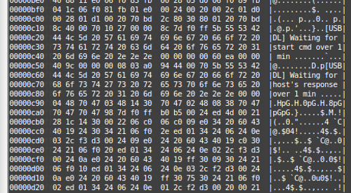
This method wasn't fast - and I suspect that the pulse lengths could be reduced somewhat - but it was getting late, and in the end I just left it running overnight. When I got up, it had stopped before the end of the 64k - however when reassembled I had a 44k file, that seemed to contain the whole rom :) - here's some strings:
SF_BOOT
BRLYT
P0Dx
[USBDL] Waiting for start cmd over 1 min ...
p[USBDL] Waiting for host's response over 1 min ...
8pGpGpG
 -JD2
KXhA
p!LD4
ACM COMMU.
ACM DATA
ACM VIRTUALCOM
RC_INIT
JM	5X
EM15M
pRESV0
H@xpG
xSxG"
pBOOTRETY
pBoot failed, reset ...
System halt!
DELY@
pUART0\
p1_ENJump to BL
MhhB
D^[a5d
pUART,\
p1_EN
xpGLI
EEEEMMM
 h,I
FILE_INFO
	HpG
SCTLCERT
"x1h
BBBB
I	h
ZZZZ
HapG
`BA02
G G(G0G8G8
"#KBC{D
Invalid Operation
Divide By Zero
Overflow
Underflow
Inexact Result
: Heap memory corrupted
Unknown signal
X65dAl
Abnormal termination
Arithmetic exception:
Illegal instruction
Interrupt received
Illegal address
Termination request
Stack overflow
Redirect: can't open:
Out of heap memory
User-defined signal 1
User-defined signal 2
Pure virtual fn called
C++ library exception
My fork of the fernly repo (including the arduino sketch) can be found here (mt6261 branch).
reverse engineering|u8plus|uart|
u8plus smart watch quick teardown and uart
9 Jan 2016

I noticed this smart watch on Amazon for the bargain price of £7.51, which was just too cheap to ignore - I didn't expect much but I was quite surprised at how functional it actually was... Anyhow, it was never expected to stay in once piece for long, and after an hour I took the screwdriver to it.
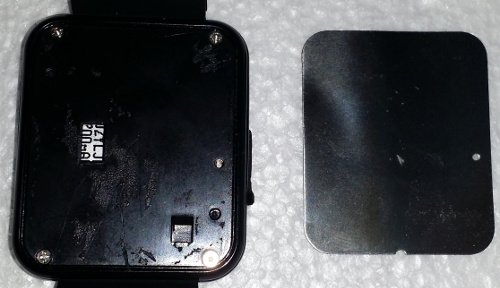
The back is covered by a aluminium plate that seemed to be sticky backed; it came off pretty easily. Underneath was four screws that released the back cover.
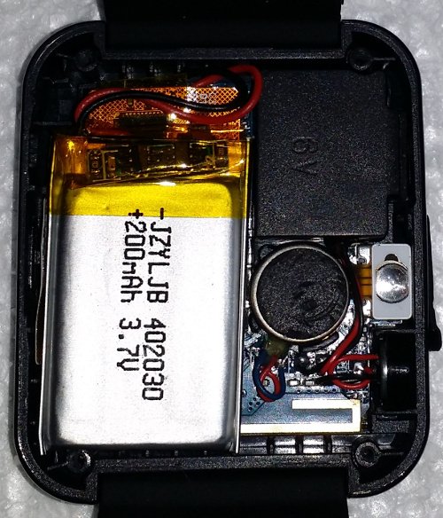
Inside, not much too see: a 200mAh, 3.7v battery, speaker, reset button (on the right) and what looks like a bluetooth antenna at the bottom.
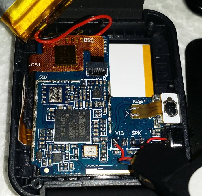
With the battery and the speaker pulled back we can see a MediaTek MT6261 SoC and supporting components on the left. On the right are connections for the reset button (mounted on top of the usb connector), speaker and what I assume is a vibrator motor connected to 'VIB'. The touchscreen is also connected at the top, with it's controller mounted on the flat flex cable. The home/power button is tucked in on the far left.
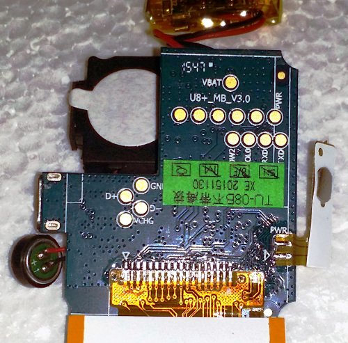
The other side of the board, removed from the shell: the connections to the LCD are at the bottom, the power button on the right and some test pads sprinkled all over :)
The 'D+' and 'D-' and the proximity to the USB suggest the four pads on the left are for the USB; VBAT is positive side of the battery; PWR connects to the power/home button. Just slightly covered by the green label is RXD and TXD - which is likely our UART, and two others ('OW2' and 'OL0'). Above them next to PWR are five unlabelled pads - hopefully these are JTAG.
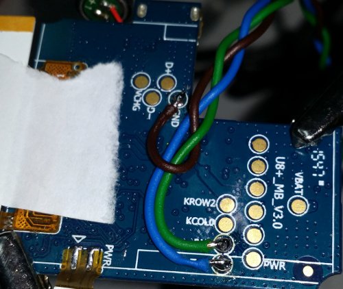
Wires connected to the GND, RXD and TXD, ready for the bus pirate. With the green label removed we can see that the two adjacent pads are actually labelled 'KROW2' and 'KCOL0'...? (I also added a scrap of sticky label to protect the LCD connections a little.)
And finally, the bootloader (@115200):
F1: 0000 0000
V0: 0000 0000 [0001]
00: 0000 0000
U0: 0000 0001 [0000]
G0: 0002 0000 [0000]
T0: 0000 00BB
Jump to BL


~~~ Welcome to MTK Bootloader V005 (since 2005) ~~~
**===================================================**


Bye bye bootloader, jump to=0x1000b5b0
reverse engineering|u8plus|uart|
totp two factor auth on tiger's wheel of fortune
24 Oct 2015
During our recent move we found an old Tiger "Wheel of Fortune" electronic game - most of my tools/toys were packed and/or moved at this point so I couldn't do much more than have a quick look inside. Last weekend I found myself wide-awake, very, very early and decided to take a closer look.
The game picks a category (phrase, person, thing etc) and an answer, then you and the cpu-controlled player two, take turns to spin the wheel and guess at the answer. There's a small number of categories built in, but more on the supplied cartridge ("Cartridge 1"). More cartridges were also available separately.
Probing the cart pins with my scope while pressing buttons, I could see that one line lit up when pressing the 'puzzle/cat./enter' button. More probing with my logic sniffer and bus pirate revealed it used a mode 1 SPI bus, with the LSB first. The read protocol is simple: a two byte address is sent by the game (via the MOSI line), and a one byte response is returned using MISO. For example here is the game (MOSI, third row) requesting the byte at 0x0 (two bytes: 0x0 and 0x0) and the cart returning 0xA5 (MISO, first row).
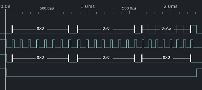
With the protocol worked out I wrote a python script to drive the bus pirate so I could sequentially read the cart's address space and dump the ROM. For dynamic analysis I also placed the dump in the progmem of an arduino mega, running a simple SPI loop that also logs all reads.
00000000  a5 01 12 3a 21 f7 1a e4  23 17 22 e9 12 39 1c 1e  |...:!...#."..9..|
00000010  16 03 01 40 06 fc 1b 25  25 25 25 25 25 25 25 25  |...@...%%%%%%%%%|
00000020  25 25 25 25 25 25 25 25  25 25 25 25 25 00 00 00  |%%%%%%%%%%%%%...|
00000030  00 00 00 00 00 00 00 00  00 00 00 00 00 00 00 00  |................|
And after running numerous tests, seems to be explained as:
0x00   0xA5 - magic byte, cart is ignored if this isn't here
0x01   0x01 - this seems to be the cart number; it's purpose is to detect if the
              cart has been changed and if so re-read 0x02(number of categories)
0x02   0x12 - number of categories (actually (n*2)-2))
0x03   0x3a - low byte of the address of the first category ('TITLE')
0x04   0x21 - high byte of the address of the first category
0x05   0xf7 - low byte of cat. 'PEOPLE'
0x06   0x1a - high byte of cat. 'PEOPLE'
0x07   0xe4 - low byte of cat. 'FICTIONAL CHARACTER'
0x08   0x23 - high byte of cat. 'FICTIONAL CHARACTER'
etc
The game cycles though each category in turn until it runs out, it then reads 0x101 and 0x102, which eventually causes it to jump back to the first entry again.
Both the categories and the answers are stored as 20 byte long arrays, that are copied to the 2x 10 char display. Initially it looked as if the chars might just be ascii, but only the vowels were decoding correctly, the other letters appeared to be missing a bit. Turns out that the vowels are 'special' and have to be bought when playing the game - the missing bit is the 'buy' flag. Interesting there's a second flag - that's not used in the game - that gives you that letter, for free, from the start:
    | |||| <<< 0 - 31 (1=A, 2=B etc)
 0001 0011
 ^^^ <<< flags
 ABC

 A = always show
 B = buy
 C = ?
There's only 32 valid characters (A-Z and a handful of symbols) and possibly a third flag ('C') - although this didn't seem to have any effect during testing.
The game picks an answer by taking the base address of the category and multiplying an internal counter by 20.
Having worked all of that out I wouldn't to be able to do something at least a little bit useful; as I could 1) detect a button press and 2) display text on the screen I thought a TOTP token might be interesting.
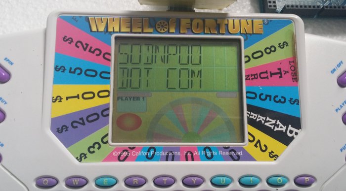
Because the game doesn't support numbers when reading from the cart - and a TOTP token is all numbers - I've had to come up with a 'creative' mapping (squint - it's almost right!):
0 -> O
1 -> I
2 -> Z
3 -> E
4 -> A
5 -> S
6 -> G
7 -> T
8 -> B
9 -> P
Here's a video showing it in action; the 'PRESS CAT FOR TOTP' message is the only answer in the embedded data, and all letters have the 'always show' bit set. The TOTP code is constantly calculated and written to a overlay variable that is read instead of the real address of the category when the button is pressed.
In a final design, the code would be installed on a ATTiny(+RTC) and placed inside a 3D printed cartridge shell, so it could quickly be swapped in when needed. An attacker looking to acquire the token would have an additional barrier of identifying the device amongst more obvious targets.
Code is hacked together from many SPI examples and Luca Dentella's TOTP code. It can be found here.
reverse engineering|tiger|wheel of fortune|
picam and generic ir array holder
27 Sept 2015
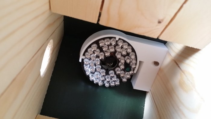
Before the new bird box goes up, it needs a camera so we can monitor any nesting activity. I like to use the raspberry pi and their camera boards; they're cheap, highly customisable (a full Linux is a very useful thing) and the rpi2 is fast enough to live stream the video.
The box has only a small hole for the birds to enter through and will be pretty dark most of the time. The 'NoIR' version on the picam is used along with a very cheap, generic, doughnut-shaped, CCTV IR LED array to deal with the lack of light. (The LED array should also provide a little extra warmth for the birds - and bugs.)
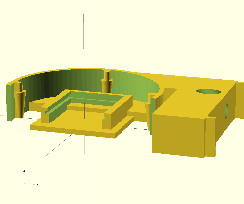
The scad code itself is split into three modules: slidein_picam(), irholder() and bracket(). Hopefully this will make things easy when I inevitably want to install another picam elsewhere. This is just the IR holder and slide in module, with just a picam installed:
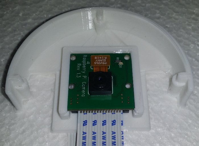
The IR array is a very snug fit and is held in place by the small amount of springiness in the two left/right 'lobes' - to install mine I needed to slightly bend the lobes out, which gives it a good, solid grip.
Finally, the bracket is a simple 'L' shape, with a 45 degree counter sunk screw hole, and two short forks that fit into grooves already cut in the bird box (in the attached scad and stl I've set them to zero length as I'm imagining a flat surface is of more use to most people).
Scad file here.
STL file here.
3d printing|scad|
1 by one doorbell (sxd043) to gpio mod
16 Aug 2015
We've recently moved house and needed a new doorbell - as I mentioned previously, I'm often working with headphones on and can easily miss a delivery, so I need to be able to trigger a real-time alert to my phone. We chose one of the many, many "1 by one" wireless, 433MHz kits (the one with the big red button).
The simpliest solution seemed to be to use an RTL SDR dongle to sniff the 433MHz band, and then trigger the existing UDP 'latch' that the code on my phone is polling for. However - for whatever reason - my SDR dongle doesn't seem to see any 433MHz traffic. (It has spent the last year living in the shed so maybe it's not so good anymore...)
A second option was to use a cheap 433MHz receiver board I have, and an arduino to do the sniffing and triggering. This sounded feasible but also sounded like mostly software dev; I write a lot of code in the day job and decided that a hardware hack would be more interesting.
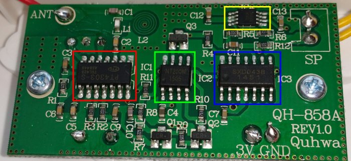
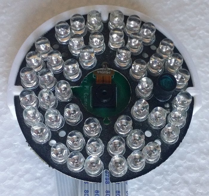
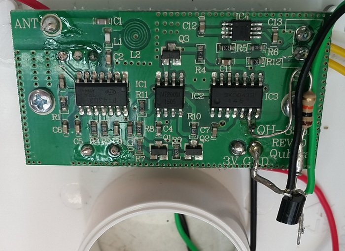
The PCB in the receiver is made up of four ICs:
- PT4303 (red) - 433MHz receiver/decoder
- NT200M (blue) - controller
- SXD043 (green) - audio
- LM4890 (yellow) - amplifier
Of these I can only find a datasheet for the TI LM4890 and a pin out diagram for the PT4303. The NT200M and the SXD043 appear to be undocumented. The board also has three buttons on the other side: learn, volume and a chime selector.
Probing the board with the scope revealed the overall design and exposed some of the power saving features (this is a battery powered receiver):
- The NT200M pulls the PT4303's CE line high briefly every second (minimising battery use by not running the receiver constantly)
- If the data sampled from the PT4303 has the learnt button code
- Trigger the SXD043 to start playing
- The SXD043 raises the LM4890's 'shutdown' line, enabling the amplifier for the duration of the audio playback (again minimising battery use by shutting down the amplifier when not playing anything)
The learn button is connected to the NT200M and when pressed, the NT200M enables the PT4303 for several seconds continuously while sampling for a new code. The volume and chime buttons are connect to the SXD043.
Based on this, two options are available: the line from the NT200M to the SXD043, essentially triggering on detection of the learnt code; or the line from the SXD043 to the LM4890's shutdown pin, triggering on any playback.
I decided to use to use the 'playback' line on the SXD043, just because it's easier to test - both the volume and chime buttons trigger playback (or I can ground the trigger line), whereas I'd need to press the doorbell - already attached to the front door frame - to test from the NT200M.
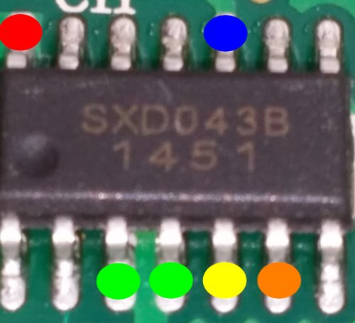
- Red - Ground
- Blue - Trigger
- Green - VCC
- Yellow - audio out
- Orange - playing
The line is fed through an NPN transistor to invert the signal, suitable to patch into the same old DG834v4's GPIO button I was using before.
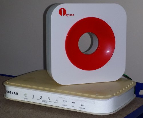
Image of the transmitter board:
doorbell|reverse engineering|