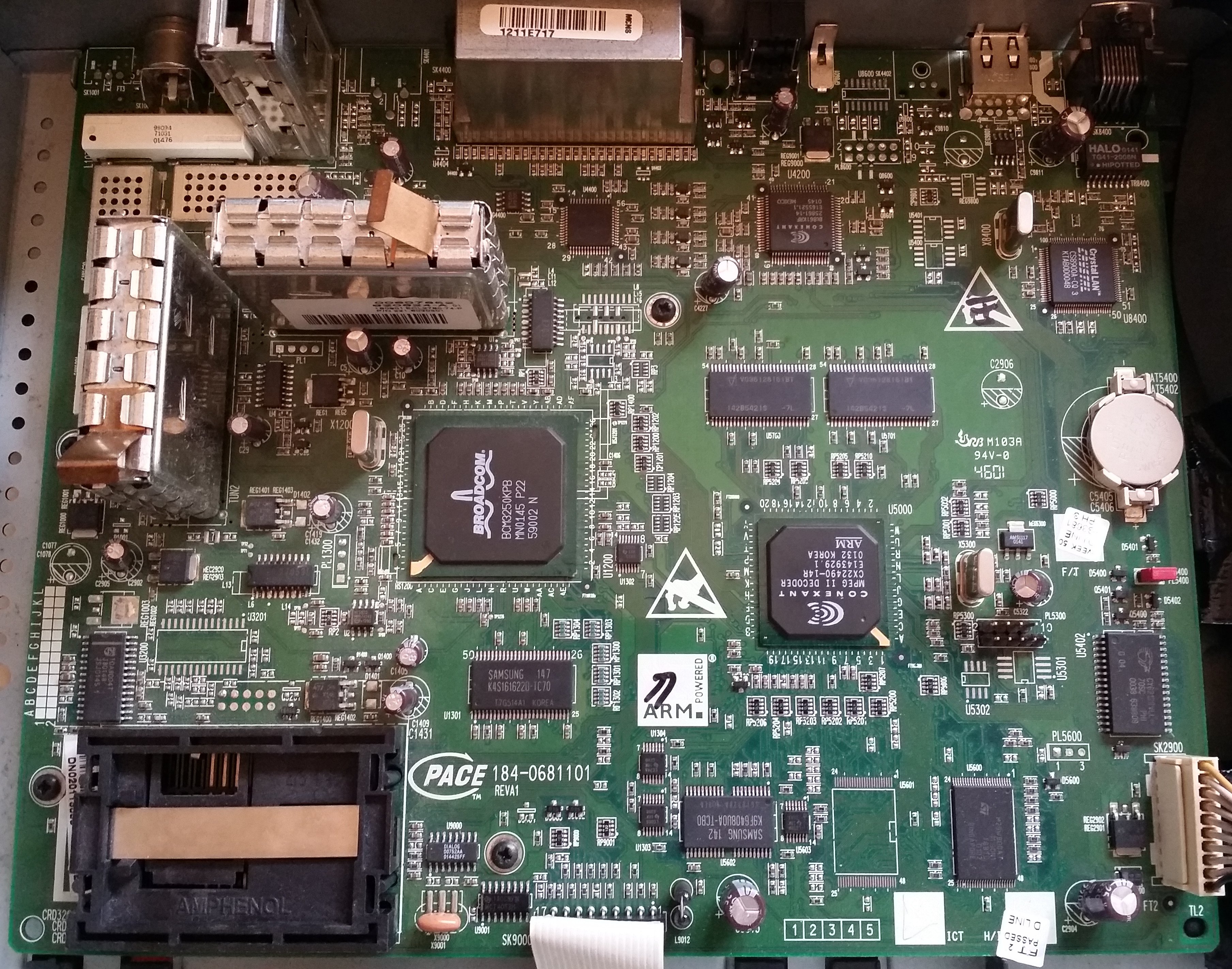
After seeing my previous work on hackaday, one of the designers of the Pace4000/Di4000 - David Fields (aka Vorchan) contacted me:
"Reading your article really took me back, 14 years ago we designed that box. It was actually called DSB for dual standard box since it was the worlds first cable box to support both DocSIS and Davic, the two cable standards at the time. It was designed to support many different cable operators around the world. Telewest and NTL (before the Virgin merger) both took boxes, from the debug you have a rebranded NTL box. The CPU is a Conexant chip (cannot remember the full number) video decoder. It runs VXWorks as the OS. The Broadcom BCM3250 chip is just the cable interface, full docsis/davic modem and video downstream tuner. The conexant CPU runs all the software."
David worked on the hardware and was able to identify some of the other pin outs on the board, and confirm my guess that PL8600 was a serial header (U8600's layout matches a MAX232):
(Click here for a large version.)
ID      Colour    Description
--      ------    -----------
PL8600  Yellow    UART - also routed to pins 10 and 12 on the SCART
                  "At boot up as part of the boot loader the box sends out a short UART message, I think AT1,
                  which when connected to a PC running some manufacturing test/service software called DigDeBug
                  would cause the PC to send back a different message that the boot loader would use to boot the
                  box into testing mode and not the normal user UI. Other than this AT command there is no other
                  debug on the UART, its all turned off."

PL1300  Blue      UART for the Broadcom cable modem chip
                  "This was used for Broadcom specific test modes to get extra cable modem debug from that processor."

PL1     Purple    I2C to control the tuners directly
                  "Used to allow RF development engineers to control the two tuners (tall metal cans) directly
                  instead of going via the Broadcom chip. This allowed for quicker bring up and test of the tuners
                  while drivers were written."

PL5600  Green     Used to change the voltage on the NOR reset pin.
                  "This allows up to temporary unlock the NOR boot loader for reprogramming."

PL5300  Red       JTAG
All of these look like interesting avenues for further research, PL8600 and PL1 initially: PL8600 can be further explored using JTAG+openocd+gdb to identify what the boot loader is sending and/or expecting to receive (more on this soon). And - making the assumption that the tuners are always controlled over the same I2C bus - I should be able to sniff PL1 using my bus pirate while forcing the box into 'tuning mode' (see here and here).
While researching what was already known about my pace 4000 box, I'd read that it could be booted into a test mode by pressing and holding the up and down buttons as you power it on. The 4x seven segment display on the front of the box changes to 'Ldr' and on the TV it shows this:
At this point the screen goes black and the front display changes to '----'. If the up/down buttons are released it runs through what I would guess is a hardware test routine; the display changes to 'PL:XX' - where XX is an incrementing two digit number - until XX is 21. It then moves onto the 'AP:XX' tests - 00 to 52 - at AP:31 a black and white Virgin media logo is shown on the TV:
If during the period '----' is displayed on the front screen, the up/down buttons continue to be pressed, the box boots instead into an 18 page diagnostic mode. The front display changes to 'diag'. Most of it is what you might expect: software versions, tuner/channel data etc - pages 9 - 12 are a bit more interesting. Here's a grab of each page:
This page almost guarantees that the bootloader contains some sort of CRC check. It also helpfully provides the exact start and end memory locations for the loader and the 'platform':
The memory map should hopefully help in locating the flash, so that over jtag I can restore the image if required:
The code 16 "Tuning parameters corrupt" events seem to relate to changes in the in-memory image caused by using soft-breakpoints; 'Err1' is displayed on the front display when that happens:
As I don't have a cable feed, the default boot actually does very little; the front panel shows 'Er11', 'Er12' then 'nit' and the TV just shows a black screen. I believe it needs to first download the 'nit' channel information from the cable network, before it will continue to the regular UI. For this reason I decided that the 'diag' mode was likely to be more interesting, but didn't really fancy having to hold the buttons down every time I wanted to reboot the box. I decided first to locate the switch point in the binary, that could be patched out when I attached openocd/gdb.
The set up is the same as I used previously: busblaster connected to the jtag pins; openocd configured to use the busblaster, with a simple arm config and listening for gdb on port 3333; and arm-none-eabi-gdb from the the gnu tools.
Openocd is executed like this, so that it halts the CPU as soon as it starts:
lee@monkeybox ~/Documents $ sudo openocd -f busblaster.cfg -f conexant_arm.cfg -c init -c halt -c targets
And gdb: connects to openocd and tells gdb how many hardware breakpoints we have:
arm-none-eabi-gdb -ex "target remote localhost:3333" -ex "set remote hardware-breakpoint-limit 2"
I'd discovered when playing with the front display that the instruction @ 0x1c240 got hit a few times during startup and that the display changed on the 11th, 31st, 40th and 82nd hit. I also knew that the 82nd hit changed text to 'nit' - which isn't shown when booting into the test modes - the switch must be before that point.
I iteratively halved the number of hits before I held down the buttons until I'd isolated that the keypress detection was between hit 35 and 36. From those two points I traced forwards/backwards (the lr register is your friend) and found this likely looking assembler:
0x00001154	0xe3a07000	MOV r7, #0x0
0x00001158	0xe3c050ff	BIC r5, r0, #0xff             <<<< r5 = r0 & 0xffffff00
0x0000115c	0xe3550e60	CMP r5, #0x600                <<<< if r5 == 0x600
0x00001160	0x0a000033	BEQ 0x00001234
0x00001164	0x8a00000c	BHI 0x0000119c
0x00001168	0xe3550f80	CMP r5, #0x200                <<<< if r5 == 0x200
0x0000116c	0x0a00001b	BEQ 0x000011e0
0x00001170	0x8a000004	BHI 0x00001188
0x00001174	0xe3550000	CMP r5, #0x0                  <<<< if r5 == 0x0
0x00001178	0x0a000014	BEQ 0x000011d0
0x0000117c	0xe3550f40	CMP r5, #0x100                <<<< if r5 == 0x100
0x00001180	0x0a000014	BEQ 0x000011d8
0x00001184	0xea00002a	B 0x00001234
0x00001188	0xe3550fc0	CMP r5, #0x300                <<<< if r5 == 0x300
0x0000118c	0x0a000017	BEQ 0x000011f0
0x00001190	0xe3550e40	CMP r5, #0x400                <<<< if r5 == 0x400
0x00001194	0x0a000017	BEQ 0x000011f8
0x00001198	0xea000025	B 0x00001234
0x0000119c	0xe3550e90	CMP r5, #0x900                <<<< if r5 == 0x900
0x000011a0	0x0a000017	BEQ 0x00001204
0x000011a4	0x8a000004	BHI 0x000011bc
0x000011a8	0xe3550e70	CMP r5, #0x700                <<<< if r5 == 0x700
0x000011ac	0x0a00000f	BEQ 0x000011f0
0x000011b0	0xe3550e80	CMP r5, #0x800                <<<< if r5 == 0x800
0x000011b4	0x0a00000c	BEQ 0x000011ec
0x000011b8	0xea00001d	B 0x00001234
0x000011bc	0xe3550ea0	CMP r5, #0xa00                <<<< if r5 == 0xa00
0x000011c0	0x0a00000a	BEQ 0x000011f0
0x000011c4	0xe3550eb0	CMP r5, #0xb00                <<<< if r5 == 0xb00
0x000011c8	0x0a000007	BEQ 0x000011ec
0x000011cc	0xea000018	B 0x00001234
Setting a breakpoint on 0x1154 revealed that r0 - before having the last eight bits masked off - is 0x300 when the box is booted normally and 0x911 when up/down is pressed. Breaking and modifying the value of r0, I could trivially boot into the diag mode, however it's quite obvious that there are more than just those two modes available.
0x0 and 0x100 don't appear to do very much, TV screen is black and the front display just shows 'Err1' (more on this later). 0x400 shows the blue 'NTL Loader' but the text has changed and we appear to have booted into an ethernet/serial download mode:
0x600 runs the into the same mode as 0x900 but doesn't show the 'NTL Loader'.
0x800 and 0xb00 display the 'NTL Loader', again text is different and the box goes into a tuning mode; first through the 'Hard Coded Channel list' and then a full scan - front display changes to Err4, Er12, Er11, nit and 'H XX' (XX: 00 - 50) for the hardcoded list and 'S XX' (XX: 00 - 89) for the scan:
0xa00 shows a black screen and just says 'nit'.
In order to gain a little more insight into the modes I've traced the first 20-30 instructions for each mode:
Each column is the sequence of instructions executed for that mode; where a short sequence (i.e. a function) is shared between two or more mode sequences they've been highlighted in the same colour. White patches are unique to that mode.
It's easy to see that the five modes (0x900, 0x200, 0x400, 0x800 and 0xb00) that display the 'NTL Loader' all call the 'blue' function - analysis of this code shows it simply sets a global flag. The flag is then read in the 'yellow' function, which returns a 0 or 1 and ultimately causes the code to branch into the purple/pink code - otherwise it ends up at brown.
0x100 clearly shows that it enters a "while(1){}" style construct @ 0x24ac and so it's understandable why it doesn't do anything. Interestingly it tries to write "Multi-ICE Download" to the TV beforehand, even though it hasn't been initialised.
0x0 does seem to be actually doing something, although as yet I haven't taken a look. Again it attempts to write a string to the TV that hints at it's real purpose: "ARM Debugger Download" :)
As you can see in the first image at the top of the page I was also able to modify the strings written to the TV. At 0x12bc I also found a call to what must be drawrect():
0x000012a0	0xe3a03c85	MOV r3, #0x8500
0x000012a4	0xe2833054	ADD r3, r3, #0x54
0x000012a8	0xe52d3004	STR r3, [r13, #-0x4]!     << r3 contains the colour
0x000012ac	0xe3a02fb4	MOV r2, #0x2d0            << r2 = 720
0x000012b0	0xe3a01000	MOV r1, #0x0              << r1 = 0
0x000012b4	0xe1a00001	MOV r0, r1                << r0 = 0
0x000012b8	0xe3a03f90	MOV r3, #0x240            << r3 = 576 - PAL :)
0x000012bc	0xeb0040e5	BL 0x00011658             << drawrect(r0, r1, r2, r3)
0x12a0 through to 0x12a8 set the 16 bit colour (might be 0xRGBA?); r2 is set to the width @ 0x12ac and r3 is set to the height @ 0x12b8 - 720x576: full screen PAL; r0 and r1 are the x and y coords. Messing with the values before the call to drawrect() let me produce these:
With the jtag pins found on the pace 4000 I though it would be nice if I could do something with it. It can (obviously) output video to a TV but I don't have a screen with a SCART input in the lab. Instead I thought I'd exercise my vanity and write my name on the 4x seven segment LED display on the front of the box.
The device is a black box with no documentation regarding the hardware, boot loader or OS. I knew that the CPU was an ARM - it has 'ARM' printed on it - which means the likely initial entry point is @ 0x0. If I halted the CPU as soon as the device was powered, I could catch it in a loop @ 0x638 where it was zeroing it's memory (adding '-c init -c halt' to the end of the openocd command line will make it halt the processor immediately) :
0x00000638	0xe8a007fc	STM r0!, {r2, r3, r4, r5, r6, r7, r8, r9, r10}
0x0000063c	0xe1500001	CMP r0, r1
0x00000640	0xbafffffc	BLT 0x00000638
From this early point in the execution I could reset the pc register back to 0x0 and step through from the start of the firmware using gdb - any later and it seems that some globals get set and interrupts have been enabled, which cause the code to branch into an infinite loop at several points.
The box runs through a handful of four char strings when it's powered on. Poking round further with gdb I eventually found a breakpoint (0x1c240) where on the 11th, 31st, 40th and 82nd hit it changes the text to '----', 'PACE', 'Err1' and 'nit' respectively. From here it jumps into a general purpose memory copy function, that reads a byte from RAM and writes it to 0x31500335:
0x0001c2e4	0xe1a0c00d	MOV r12, r13
0x0001c2e8	0xe92dd800	STMDB r13!, {r11, r12, r14, r15}
0x0001c2ec	0xe59f3030	LDR r3, [r15, #0x30]
0x0001c2f0	0xe24cb004	SUB r11, r12, #0x4
0x0001c2f4	0xe3a0c000	MOV r12, #0x0
0x0001c2f8	0xe5933000	LDR r3, [r3]
0x0001c2fc	0xe15c0001	CMP r12, r1
0x0001c300	0xe0800003	ADD r0, r0, r3
0x0001c304	0x2a000004	BCS 0x0001c31c
0x0001c308	0xe4d23001	LDRB r3, [r2], #0x1  <<< read from RAM @r2 into r3
0x0001c30c	0xe4c03001	STRB r3, [r0], #0x1  <<< write r3 to @r0 (0x31500335)
As soon as the STRB (SToRe Byte) command was executed the display changed. Stepping back and forth over 0x1c30c changing the value r3 revealed something interesting: the bottom half of the first two of the segments changed and the bottom of segments three and four changed to what one and two had just been - more iterations showed changes to the top half's, along with the colon in the middle and the three status LEDs on the right.
It was now apparent that the display was split into four sections and I could simply write each section in turn, by writing four times to 0x31500335, pushing the data round anti-clockwise until I had updated the whole display. I'd noticed though, that this wasn't what happened when the display was updated by the firmware; the whole display updated in one go.
Taking a look at the 10th hit of 0x1c240 showed that another byte was being written to the address before the one in the 11th call (@0x31500334). Changes here didn't affect the display until the 11th break on 0x1c240. At this point I wrongly assumed that the display could be addressed by writing to 0x31500332, 0x31500333, 0x31500334 and 0x31500335 - where the '335 write also updated the screen. By Examining the two hits before it was demonstrated that the sequence was in fact: three writes to '334 and a final write to '335 to update the screen - all the writes caused a shift round to the next section; these gdb commands will update the whole display:
set $pc = 0x1c30c
set $r0 = 0x31500334
set $r3 = 0xff
ni

set $pc = 0x1c30c
set $r0 = 0x31500334
set $r3 = 0xff
ni

set $pc = 0x1c30c
set $r0 = 0x31500334
set $r3 = 0xff
ni

set $pc = 0x1c30c
set $r0 = 0x31500335
set $r3 = 0xff
ni
In the above 'map' you can see the four sections - red, blue, green and pink - of a byte each, where every bit corresponds to an individual segment (A-H). Note that the two LEDs that make up the colon between the two '88' digits are addressed as a single bit (A). As an added complication bits A-C and F-H are inverted i.e. you set them off to light them up; D and E are the other way around:
          ABCDEFGH
0xe7    0b11100111    A-H off
0x18    0b00011000    A-H on
Writing to the segments is done by first writing in turn pink, then green and blue to 0x31500334. Then finally red to 0x31500335 which will also update the display.
I now had enough information to program the display and after working out the values based on the map I could write my name using this:
set $pc = 0x1c30c
set $r0 = 0x31500334
set $r3 = 0xfb
ni

set $pc = 0x1c30c
set $r0 = 0x31500334
set $r3 = 0xd7
ni

set $pc = 0x1c30c
set $r0 = 0x31500334
set $r3 = 0xe0
ni

set $pc = 0x1c30c
set $r0 = 0x31500335
set $r3 = 0x01
ni
My expectation was that these byte values would be pre-calculated and hardcoded somewhere in the firmware image but I couldn't find them. I noticed in the 'strings' output the four char strings I had been seeing on the display:
PRIMARY LOADER
Ldr
Err1                                <<<
RAM Fail
Err2
**********NVRAM Fail***********
Err3
FLASH Fail
Er40
Cache Initialise Fail
LED Initialise Fail
PACE                                <<<
Key Initialise Fail
I2C Initialise Fail
Graphics Initialise Fail
DENC Initialise Fail
SCART Initialise Fail
REMOD Initialise Fail
Engineering mode
Failed to read keys
ENGINEERING MODE:
0000
0000
Found platform
Decompressed platform
FAILED TO GET PROTECTED CONFIGURATION DATA
----                                <<<
I was interested to see how the conversion was done so I set a rwatch breakpoint on the address of 'PACE'. The process is split into two parts, the first part takes each of the four chars in turn and uses their value as an index into this lookup table:
0x0001fc04: 4d 42 4d 32 39 4c 56 36 35 31 20 28 57 41 52 4e 49 4e 47 3a 20 55 6e 74 65 73 74 65 64 29 00 00
0x0001fc24: 00 00 00 00 00 00 00 00 00 00 00 00 00 40 00 00 3f 06 5b 4f 66 6d 7d 07 7f 6f 00 00 00 00 00 00
               A  B  C  D  E  F  G  H  I  J  K  L  M  N  O  P  Q  R  S  T  U  V  W  X  Y  Z
0x0001fc44: 00 77 7f 39 3f 79 71 3d 76 06 1f 00 38 00 37 3f 73 67 50 6d 78 3e 00 00 00 66 00 79 64 4f 00 08
               a  b  c  d  e  f  g  h  i  j  k  l  m  n  o  p  q  r  s  t  u  v  w  x  y  z
0x0001fc64: 00 5f 7c 58 5e 7b 71 6f 74 04 0e 00 06 00 54 5c 73 67 50 6d 78 1c 00 00 00 6e 00 00 30 00 40 00
0x0001fc84: 01 01 01 00 80 01 80 00 2d 2d 2d 2d 00 00 00 00 00 00 00 00 b7 1d c1 04 6e 3b 82 09 d9 26 43 0d
0x0001fca4: dc 76 04 13 6b 6b c5 17 b2 4d 86 1a 05 50 47 1e b8 ed 08 26 0f f0 c9 22 d6 d6 8a 2f 61 cb 4b 2b
0x0001fcc4: 64 9b 0c 35 d3 86 cd 31 0a a0 8e 3c bd bd 4f 38 70 db 11 4c c7 c6 d0 48 1e e0 93 45 a9 fd 52 41
0x0001fce4: ac ad 15 5f 1b b0 d4 5b c2 96 97 56 75 8b 56 52 c8 36 19 6a 7f 2b d8 6e a6 0d 9b 63 11 10 5a
These byte values represent which parts of an individual seven-segment to light up:
  7654321
0b1111111

 1
6 2
 7
5 3
 4
'PACE' is translated to: 73 77 39 79 and looks like this:
         7654321
P 0x73 0b1110011
A 0x77 0b1110111
C 0x39 0b0111001
E 0x79 0b1111001

 1     1     1     1
6 2   6 2   6     6
 7     7           7
5     5 3   5     5
             4     4
The second part of the process uses masking and shifting to map the idealised representation of the bit sequences to the four coloured sections mapped out earlier. The four chars are first reversed (e.g. 0x79773979 becomes 0x79397779) and then split into two 16 bit words i.e. as 0xAAAABBBB.
Each of A and B are further split into 0xXXYY and bits 1, 2 and 6 from both X and Y (which are the top half of the letters) are shifted into place as the pink and green sections. Bits 3, 4, 5 and 7 (the bottom half's) - again from both X and Y - are shifted to become the red and blue sections. The final values are then xor'd against 0xe7 to flip the inverted (A-C and F-H) bits.
The following python was written against the assembler to validate the approach:
#python implementation of the PACE 4000 ASCII to 88:88 display.
#
#It first reads the 4 char ASCII string and maps that to this lookup table (base+char):
'''
0x0001fc04: 4d 42 4d 32 39 4c 56 36 35 31 20 28 57 41 52 4e 49 4e 47 3a 20 55 6e 74 65 73 74 65 64 29 00 00
0x0001fc24: 00 00 00 00 00 00 00 00 00 00 00 00 00 40 00 00 3f 06 5b 4f 66 6d 7d 07 7f 6f 00 00 00 00 00 00
0x0001fc44: 00 77 7f 39 3f 79 71 3d 76 06 1f 00 38 00 37 3f 73 67 50 6d 78 3e 00 00 00 66 00 79 64 4f 00 08
0x0001fc64: 00 5f 7c 58 5e 7b 71 6f 74 04 0e 00 06 00 54 5c 73 67 50 6d 78 1c 00 00 00 6e 00 00 30 00 40 00
0x0001fc84: 01 01 01 00 80 01 80 00 2d 2d 2d 2d 00 00 00 00 00 00 00 00 b7 1d c1 04 6e 3b 82 09 d9 26 43 0d
0x0001fca4: dc 76 04 13 6b 6b c5 17 b2 4d 86 1a 05 50 47 1e b8 ed 08 26 0f f0 c9 22 d6 d6 8a 2f 61 cb 4b 2b
0x0001fcc4: 64 9b 0c 35 d3 86 cd 31 0a a0 8e 3c bd bd 4f 38 70 db 11 4c c7 c6 d0 48 1e e0 93 45 a9 fd 52 41
0x0001fce4: ac ad 15 5f 1b b0 d4 5b c2 96 97 56 75 8b 56 52 c8 36 19 6a 7f 2b d8 6e a6 0d 9b 63 11 10 5a

the lookup table describes the individual LEDs that need to be lit up to show the letter - for an idealised display.

However the PACE4000 display is wacky (the digits are across byte boundaries - split around the middle and need to be shifted in) and so we then need to mangle it using masking/shifting to give us the four bytes we need to shift in.

 -   -
| | | |
 -   -
| | | |
 -   -

lookup table bit pattern:
 1
6 2
 7
5 3
 4

'''

lookup = [
  0x4d, 0x42, 0x4d, 0x32, 0x39, 0x4c, 0x56, 0x36, 0x35, 0x31, 0x20, 0x28, 0x57, 0x41, 0x52, 0x4e, 0x49, 0x4e,
  0x47, 0x3a, 0x20, 0x55, 0x6e, 0x74, 0x65, 0x73, 0x74, 0x65, 0x64, 0x29, 0x00, 0x00, 0x00, 0x00, 0x00, 0x00,
  0x00, 0x00, 0x00, 0x00, 0x00, 0x00, 0x00, 0x00, 0x00, 0x40, 0x00, 0x00, 0x3f, 0x06, 0x5b, 0x4f, 0x66, 0x6d,
  0x7d, 0x07, 0x7f, 0x6f, 0x00, 0x00, 0x00, 0x00, 0x00, 0x00, 0x00,
 0x77, #A
 0x7f, #B
 0x39, #C
 0x3f, #D
 0x79, #E
 0x71, #F
 0x3d, #G
 0x76, #H
 0x06, #I
 0x1f, #J
 0x00, #K
 0x38, #L
 0x00, #M
 0x37, #N
 0x3f, #O
 0x73, #P
 0x67, #Q
 0x50, #R
 0x6d, #S
 0x78, #T
 0x3e, #U
 0x00, #V
 0x00, #W
 0x00, #X
 0x66, #Y
 0x00, #Z
 0x79,
 0x64,
 0x4f,
 0x00,
 0x08,
 0x00,
 0x5f, #a
 0x7c, #b
 0x58, #c
 0x5e, #d
 0x7b, #e
 0x71, #f
 0x6f, #g
 0x74, #h
 0x04, #i
 0x0e, #j
 0x00, #k
 0x06, #l
 0x00, #m
 0x54, #n
 0x5c, #o
 0x73, #p
 0x67, #q
 0x50, #r
 0x6d, #s
 0x78, #t
 0x1c, #u
 0x00, #v
 0x00, #w
 0x00, #x
 0x6e, #y
 0x00, #z
 0x00, 0x30, 0x00, 0x40, 0x00, 0x01, 0x01, 0x01, 0x00, 0x80, 0x01, 0x80, 0x00, 0x2d, 0x2d, 0x2d, 0x2d, 0x00,
 0x00, 0x00, 0x00, 0x00, 0x00, 0x00, 0x00, 0xb7, 0x1d, 0xc1, 0x04, 0x6e, 0x3b, 0x82, 0x09, 0xd9, 0x26, 0x43,
 0x0d, 0xdc, 0x76, 0x04, 0x13, 0x6b, 0x6b, 0xc5, 0x17, 0xb2, 0x4d, 0x86, 0x1a, 0x05, 0x50, 0x47, 0x1e, 0xb8,
 0xed, 0x08, 0x26, 0x0f, 0xf0, 0xc9, 0x22, 0xd6, 0xd6, 0x8a, 0x2f, 0x61, 0xcb, 0x4b, 0x2b, 0x64, 0x9b, 0x0c,
 0x35, 0xd3, 0x86, 0xcd, 0x31, 0x0a, 0xa0, 0x8e, 0x3c, 0xbd, 0xbd, 0x4f, 0x38, 0x70, 0xdb, 0x11, 0x4c, 0xc7,
 0xc6, 0xd0, 0x48, 0x1e, 0xe0, 0x93, 0x45, 0xa9, 0xfd, 0x52, 0x41, 0xac, 0xad, 0x15, 0x5f, 0x1b, 0xb0, 0xd4,
 0x5b, 0xc2, 0x96, 0x97, 0x56, 0x75, 0x8b, 0x56, 0x52, 0xc8, 0x36, 0x19, 0x6a, 0x7f, 0x2b, 0xd8, 0x6e, 0xa6,
 0x0d, 0x9b, 0x63, 0x11, 0x10, 0x5a]


s = 'PACE'
#s = 'LEE '

m = 0
shift = 0
for c in s:
  i = ord(c)
  #print i
  #print hex(lookup[i])
  m = m | (int(lookup[i]) << shift)
  shift += 8

#print "m:", hex(m)
r0 = m

#r0 = 0x79397773
#expected = 99 db 01 34


#there are 4 segments:

#pink segment - uses last two bytes i.e. 0x????XXYY (Y=1st, X=2nd)
#top half of digits one and two
#bits 1, 2 and 6 are the top half in the source bytes (XX and YY)

#extract bit 6 from XX
r2 = r0 & 0x2000        #0x0000c8a4	0xe2002d80	AND r2, r0, #0x2000
r2 = r2 >> 0xa          #0x0000c8a8	0xe1a02522	MOV r2, r2, LSR #0xa
#extract bits 1 and 2 from YY
r3 = r0 & 0x3           #0x0000c8ac	0xe2003003	AND r3, r0, #0x3
r3 = r3 << 0x5          #0x0000c8b0	0xe1a03283	MOV r3, r3, LSL #0x5
r2 = r2 | r3            #0x0000c8b4	0xe1822003	ORR r2, r2, r3
#extract bit 6 from YY
r3 = r0 & 0x20          #0x0000c8b8	0xe2003020	AND r3, r0, #0x20
r3 = r3 >> 0x1          #0x0000c8bc	0xe1a030a3	MOV r3, r3, LSR #0x1
r2 = r2 | r3            #0x0000c8c0	0xe1822003	ORR r2, r2, r3
#extract bit 1 from XX
r3 = r0 & 0x100         #0x0000c8c4	0xe2003f40	AND r3, r0, #0x100
r3 = r3 >> 0x6          #0x0000c8c8	0xe1a03323	MOV r3, r3, LSR #0x6
r2 = r2 | r3            #0x0000c8cc	0xe1822003	ORR r2, r2, r3
#extract bit 2 from XX
r3 = r0 & 0x200         #0x0000c8d0	0xe2003f80	AND r3, r0, #0x200
r3 = r3 >> 0x8          #0x0000c8d4	0xe1a03423	MOV r3, r3, LSR #0x8
r2 = r2 | r3            #0x0000c8d8	0xe1822003	ORR r2, r2, r3
#flip the inverted bits
r2 = r2 ^ 0xe7          #0x0000c8dc	0xe22220e7	EOR r2, r2, #0xe7
print "pink: ",hex(r2)

#red segment - uses last two bytes i.e. 0x????XXYY (Y=1st, X=2nd)
#bottom half of digits one and two
#bits 3, 4, 5 and 7 are the bottom half in the source bytes (XX and YY)

#extract bit 3 from YY
r3 = r0 & 0x4           #0x0000c8e4	0xe2003004	AND r3, r0, #0x4
#extract bit 4 from YY
r2 = r0 & 0x8           #0x0000c8e8	0xe2002008	AND r2, r0, #0x8
r2 = r2 >> 0x1          #0x0000c8ec	0xe1a020a2	MOV r2, r2, LSR #0x1
r2 = r2 | (r3 << 0x1)   #0x0000c8f0	0xe1822083	ORR r2, r2, r3, LSL #0x1
#extract bit 5 from YY
r3 = r0 & 0x10          #0x0000c8f4	0xe2003010	AND r3, r0, #0x10
r3 = r3 >> 0x3          #0x0000c8f8	0xe1a031a3	MOV r3, r3, LSR #0x3
r2 = r2 | r3            #0x0000c8fc	0xe1822003	ORR r2, r2, r3
#extract bit 7 from YY and bits 3, 4 and 5 from XX
r3 = r0 & 0x1c40        #0x0000c900	0xe2003d71	AND r3, r0, #0x1c40
r2 = r2 | (r3 >> 0x6)   #0x0000c904	0xe1822323	ORR r2, r2, r3, LSR #0x6
#extract bit 7 from XX
r3 = r0 & 0x4000        #0x0000c908	0xe2003c40	AND r3, r0, #0x4000
r3 = r3 >> 0x7          #0x0000c90c	0xe1a033a3	MOV r3, r3, LSR #0x7
r2 = r2 | r3            #0x0000c910	0xe1822003	ORR r2, r2, r3
#flip the inverted bits
r2 = r2 ^ 0xe7          #0x0000c914	0xe22220e7	EOR r2, r2, #0xe7
print "red:  ",hex(r2)

#green segment - uses first two bytes i.e. 0xXXYY???? (Y=3rd, X=4th)
#top half of digits three and four
#bits 1, 2 and 6 are the top half in the source bytes (XX and YY)

#shift r0 16 bits, so that it's just working on 0xXXXX
r0 = r0 >> 0x10         #0x0000c91c	0xe1a00820	MOV r0, r0, LSR #0x10
#extract bits 1 and 2 from YY
r3 = r0 & 0x3           #0x0000c920	0xe2003003	AND r3, r0, #0x3
r3 = r3 << 0x5          #0x0000c924	0xe1a03283	MOV r3, r3, LSL #0x5
#extract bit 6 from XX
r2 = r0 & 0x2000        #0x0000c928	0xe2002d80	AND r2, r0, #0x2000
r2 = r2 >> 0xa          #0x0000c92c	0xe1a02522	MOV r2, r2, LSR #0xa
r2 = r2 | r3            #0x0000c930	0xe1822003	ORR r2, r2, r3
#extract bit 6 from YY
r3 = r0 & 0x20          #0x0000c934	0xe2003020	AND r3, r0, #0x20
r3 = r3 >> 0x1          #0x0000c938	0xe1a030a3	MOV r3, r3, LSR #0x1
r2 = r2 | r3            #0x0000c93c	0xe1822003	ORR r2, r2, r3
#extract bit 1 from XX
r3 = r0 & 0x100         #0x0000c940	0xe2003f40	AND r3, r0, #0x100
r3 = r3 >> 0x6          #0x0000c944	0xe1a03323	MOV r3, r3, LSR #0x6
r2 = r2 | r3            #0x0000c948	0xe1822003	ORR r2, r2, r3
#extract bit 2 from XX
r3 = r0 & 0x200         #0x0000c94c	0xe2003f80	AND r3, r0, #0x200
r3 = r3 >> 0x8          #0x0000c950	0xe1a03423	MOV r3, r3, LSR #0x8
r2 = r2 | r3            #0x0000c954	0xe1822003	ORR r2, r2, r3
#flip the inverted bits
r2 = r2 ^ 0xe7          #0x0000c958	0xe22220e7	EOR r2, r2, #0xe7
print "green:",hex(r2)

#blue segment - uses first two bytes i.e. 0xXXYY???? (Y=3rd, X=4th)
#bottom half of digits three and four
#bits 3, 4, 5 and 7 are the bottom half in the source bytes (XX and YY)

#extract bit 3 from YY
r3 = r0 & 0x4           #0x0000c964	0xe2003004	AND r3, r0, #0x4
#extract bit 4 from YY
r2 = r0 & 0x8           #0x0000c968	0xe2002008	AND r2, r0, #0x8
r2 = r2 >> 0x1          #0x0000c96c	0xe1a020a2	MOV r2, r2, LSR #0x1
r2 = r2 | (r3 << 0x1)   #0x0000c970	0xe1822083	ORR r2, r2, r3, LSL #0x1
#extract bit 5 from YY
r3 = r0 & 0x10          #0x0000c974	0xe2003010	AND r3, r0, #0x10
r3 = r3 >> 0x3          #0x0000c978	0xe1a031a3	MOV r3, r3, LSR #0x3
r2 = r2 | r3            #0x0000c97c	0xe1822003	ORR r2, r2, r3
#extract bit 7 from YY and bits 3, 4 and 5 from XX
r3 = r0 & 0x1c40        #0x0000c980	0xe2003d71	AND r3, r0, #0x1c40
r2 = r2 | (r3 >> 0x6)   #0x0000c984	0xe1822323	ORR r2, r2, r3, LSR #0x6
#extract bit 7 from XX
r0 = r0 & 0x4000        #0x0000c988	0xe2000c40	AND r0, r0, #0x4000
r0 = r0 >> 0x7          #0x0000c98c	0xe1a003a0	MOV r0, r0, LSR #0x7
r2 = r2 | r0            #0x0000c990	0xe1822000	ORR r2, r2, r0
#flip the inverted bits
r2 = r2 ^ 0xe7          #0x0000c994	0xe22220e7	EOR r2, r2, #0xe7
print "blue :",hex(r2)
After having success finding the jtag pads on an old router, I turned my attention to some of the other old kit I have lying around. I'd had the lid off the Virgin-branded, Pace 4000 set top box previously and noticed that it had a handful of unpopulated headers on the board. The nine closest to the CPU seemed most promising, so after soldering some pins, checking the voltages (all within 3.3v) and for ground, I attached my arduino mega running jtagenum. It found this:
#   JTAG  colour
9   TDO   red
7   TCK   blue
5   TMS   green
3   TDI   pink
Using openocd I was able to hack together this config file for the Conexant 'MPEG II DECODER' ARM chip:
set _CHIPNAME conexantarm
set _CPUID 0x10940027

jtag newtap $_CHIPNAME cpu -expected-id $_CPUID -irlen 4

set _TARGETNAME $_CHIPNAME.cpu
target create $_TARGETNAME arm920t -endian little -chain-position $_TARGETNAME
Dumping from 0x0, the first 256 bytes:
lee@monkeybox ~/Downloads/openocd/openocd $ hexdump -C pace-virgin.bin | less
00000000  18 f0 9f e5 18 f0 9f e5  18 f0 9f e5 18 f0 9f e5  |................|
*
00000020  08 01 00 00 78 01 00 00  84 01 00 00 f4 01 00 00  |....x...........|
00000030  00 02 00 00 0c 02 00 00  18 02 00 00 24 02 00 00  |............$...|
00000040  2e 97 a0 a9 ba f4 a7 d4  30 5f 80 35 0e c3 bc 77  |........0_.5...w|
00000050  7c 57 55 68 dc 59 be f6  24 ae d1 52 85 62 c7 8d  ||WUh.Y..$..R.b..|
00000060  83 e2 75 03 75 29 e6 11  00 00 04 00 fc ff 03 00  |..u.u)..........|
00000070  00 00 00 20 00 00 00 00  00 00 00 00 00 00 00 00  |... ............|
00000080  08 08 00 00 00 00 00 00  00 00 6c 6f 61 64 65 72  |..........loader|
00000090  00 00 00 5f 37 37 37 37  37 37 37 37 37 37 37 37  |..._777777777777|
000000a0  37 37 37 37 37 37 37 37  37 37 37 37 37 37 37 37  |7777777777777777|
000000b0  37 37 37 37 37 37 37 37  37 37 37 37 2b f7 9f f4  |777777777777+...|
000000c0  4e 54 4c 20 4c 6f 61 64  65 72 20 56 31 2e 39 20  |NTL Loader V1.9 |
000000d0  52 65 6c 65 61 73 65 00  00 00 00 00 00 00 00 00  |Release.........|
000000e0  00 00 00 00 00 00 00 00  00 00 00 00 00 00 00 00  |................|
And through 'strings' (anyone else think the passcode for 'ENGINEERING MODE' might be '0000'? ;) ):
Stopping off air download
Paul's debug loader
BUILDING FAT:
Ethernet Download Not Avaliable
Changing to serial download
Serial Download
Skipping Download
RUN PLATFORM
FAIL
Invalid platform flash is set. Deleting non platform objects
Deleted flash object of type
Failed to delete flash object, error is
pstHeader is
Object size is
CRC offset is
*****************************************************************

PRIMARY LOADER
Ldr
Err1
RAM Fail
Err2
**********NVRAM Fail***********
Err3
FLASH Fail
Er40
Cache Initialise Fail
LED Initialise Fail
PACE
Key Initialise Fail
I2C Initialise Fail
Graphics Initialise Fail
DENC Initialise Fail
SCART Initialise Fail
REMOD Initialise Fail
Engineering mode
Failed to read keys
ENGINEERING MODE:
0000
0000