We've had a robot vacuum at home for a couple of months and now we've got one for the office at work. The XR at home came with a virtual wall that produces an infrared beam that the vacuum just wont go anywhere near. The Vileda at work didn't come with one (nor a remote or a dock) which would of been handy; there's a couple of areas we'd like to keep it away from.
On the front of the Vileda there's a 360 degree IR sensor that both my XR and the Roomba's have - although the Vileda doesn't come with any accessories that it would need it for (dock, virtual wall) - nor at present does Vileda appear to sell any. Making the assumption that both of these had probably been - for at least some part - reverse engineered from a Roomba, I took the virtual wall from home into work and tested it against the Vileda; it too wouldn't go any where near it :)
I'm not really allowed to open up the the XR (or it's accessories) at home as it's technically "in production", but initial thoughts were that I just needed to be able to detect the beam coming from the virtual wall myself and then re-create it. Before doing that though I thought I'd see if the Roomba virtual wall had been reverse engineered already and see if I could implement that, and if it caused the XR to flee.
After a little searching I found this post that details some of the IR protocol used on the Roomba's - and right at the bottom of the page there is this:"The Virtual Walls generate a 1ms ON, 1ms OFF signal continuously. The 1ms ON is a 38Khz PWM pulse."
Excellent. A little more searching and I found this post on the arduino forums; right at the bottom of the code block there's this function:
// this will write an oscillation at 38KHz for a certain time in useconds
void oscillationWrite(int pin, int time) {
 for(int i = 0; i <= time/26; i++) {
   digitalWrite(pin, HIGH);
   delayMicroseconds(13);
   digitalWrite(pin, LOW);
   delayMicroseconds(13);
 }
}
So I swiped an IR LED from an old TV remote and after a bit of messing with my phones camera (it doesn't have an IR filter so I could use it to see the infrared) and the blink example program, I wrapped oscillationWrite() up in loop() so that it did a 38KHz pulse every millisecond:
void loop() {
  oscillationWrite(irled, 1000);
  delayMicroseconds(1000);
}
I was pretty hopeful that this would work and went to test it with the XR, but it completely ignored it. Assuming one of the timings was off I hooked the scope to the LED pins. The millisecond pulse was a little off but not by a lot, but the 13 microsecond pulses that make up the 38KHz carrier were coming in at 18 microseconds, probably due to the amount of code that's executed by digitalWrite(). Rather than mess around using port manipulation to speed up toggling the pin, I just knocked the delay time down to 8us to compensate.
Testing again with the XR proved successful, with it backing away whenever it got to close to my improvised beam :) for a complete test I trapped the XR between my beam and the virtual wall it came with. My 'wall' is across the bottom of the door next to the olde worlde CD player and the real one is the black object on the floor next to the sofa. Everytime it sees a beam, it backs away. (The bumper is actually at the front - it's just that in the video, the XR spends most of it's time going backwards!)
Although I now had a working solution I couldn't help but think that the hardware PWM could generate the carrier more accurately than rapidly toggling a pin. Yet more searching brought up this this post that suggested a wonderful simple solution:
"Why not just use the Tone() function?"
Swapping out oscillationWrite() for tone() works perfectly and results in this very concise sketch:
int irled = 40;

void setup() {
  pinMode(irled, OUTPUT);
}

void loop() {
  tone(irled, 38000, 1);
  delayMicroseconds(1000);
}
Hardware-wise, it's nothing special; just an IR LED with it's positive leg connected via a current-limiting resistor to the +5v, and it's negative leg to any pin you like. (Pin 40 for me, using a Mega.)
After a long time without any sort of attention, the weathoscope has had a bit of an overhaul. A few months ago I rewrote the web UI, mostly just to use jQuery and flot rather than the Google charts API. The BMP085 pressure sensor breakout board I was playing with back in March has been integrated. Here it is on the breadboard:
And here it is wrapped in some heat shrink tubing for protection. There's a square hole cut in the tubing with a scalpel to expose the actual sensor. (The white stuff is the remnants of a piece of sticky foam pad; I forgot to take a picture before sticking it down...)
Although the BMP085 is a pressure sensor it also provides a digital temperature output - as this is factory calibrated it has replaced the readings I was previously getting using a LM335Z. The LM335Z is still connected and logged, I just don't use the values in the front end.
The anemometer is the device I first made back in December 2010. It's only recently come into service with some cups taken from a basic weather station kit - it originally had some home made blades but these were just rubbish; they didn't really turn easily and fell apart in the end.
Inside the blue box, at the other end of the axle is a cog with a single hole, an infrared LED and light dependant resistor. The LDR is connected to one of the arduino's interrupt pins and gets triggered when the hole is between the LED and the LDR. I.e. once per revolution. Using the radius of the cups and the count of the revolutions over a known time period we can calculate the wind speed.
Software The software stack comprises of the arduino code that deals with the individual sensors, then outputs a set of key value pairs on the uart (once per minute). This is read by a perl script running on the host PC that parses and inserts the readings into a postgres database. A recent amendment makes this script pushes the data up to OpenWeatherMap too.
On the front end web server there's a small PHP script that acts as a simple RPC wrapper around the DB. It'll take one of the date ranges (day, week, month etc) and output a JSON-ified object ready for feeding into flot. Finally there's a bit of jQuery combined with flot to draw the graphs. APC is used to cache the results from the DB to avoid hitting the DB too often.
The latest code needs a bit of a clean up before I can release it; hopefully get it posted in the next week or so.
Plans Current plans include extending the system with a humidity sensor, replace the light sensor that has corroded away and maybe once the 3D printer arrives, build a tipping bucket rain gauge.
Web UI is here. To see the other weathoscope related posts click the 'weathoscope' tag at the bottom of the page (or click here).
The code at the bottom of this post is a modification of RFIDIOt's ChAP.py to use Mako's iso7816 arduino interface instead of pyscard. It's based on the code I wrote recently and let's you read EMV/Chip and pin cards with just an arduino as the hardware interface. In the above image of one of my homemade breadboard arduino's, the 5 wires are connected directly to the relevant contacts on the card - no external parts required. Example of the first 20ish lines of output:
PSE found!
  6f: File Control Information (FCI) Template (36 bytes):
     84: DF Name (14 bytes):
     a5: Proprietary Information (18 bytes):
        88: Short File Identifier (1 bytes): 01
        bf0c: File Control Information (FCI) Issuer Discretionary Data (12 bytes): skipping BER-TLV object!
  Checking for records:
  Record 01, File 01: length 34
      AID found: a0 00 00 00 05 00 01
  Record 02, File 01: length 33
      AID found: a0 00 00 00 24 01
  Record 03, File 01: length 34
      AID found: a0 00 00 00 29 10 10
  Record 04, File 01: length 34
      AID found: a0 00 00 00 04 30 60
  Found AID: Maestro - a0 00 00 00 04 30 60
  6f: File Control Information (FCI) Template (47 bytes):
     84: DF Name (7 bytes):
     a5: Proprietary Information (36 bytes):
        50: Application Label (16 bytes): Maestro
        87: Application Priority Indicator (1 bytes): skipping BER-TLV object!
  Processing Options:   80: Response Message Template Format 1 (14 bytes): 5c 00 08 01 01 00 10 01 03 01 18 01 03 00
    Cardholder verification is supported
    Issuer authentication is supported
    Terminal risk management is to be performed
The changes to ChAP.py are mainly just the actual transmit functions and a little bit of initialisation. Although v0.1c appears to have PIN VERIFY I couldn't get this to work; it may be just that I can't actually remember the PINs to the old cards I'm testing with but it appears the card didn't actually send a bad PIN response. They did however decrement the PIN tries counter...
To use you need to upload Mako's sketch to a 328 based arduino, connect the EMV card as:
#! /usr/bin/env python
"""
Script that tries to select the EMV Payment Systems Directory
using Mako's iso7816 arduino interface
http://www.makomk.com/2011/02/25/iso-7816-smartcard-interface-for-arduino/
  Copyright 2013 Lee Bowyer
  http://www.sodnpoo.com/posts.xml/reading_emv(chip_and_pin)_cards_with_an_arduino.xml

This file is based on ChAP.py from RFIDIOt.
  Copyright 2008 RFIDIOt
  Author: Adam Laurie, mailto:adam@algroup.co.uk
	  http://rfidiot.org/ChAP.py

This file is based on an example program from scard-python.
  Originally Copyright 2001-2007 gemalto
  Author: Jean-Daniel Aussel, mailto:jean-daniel.aussel@gemalto.com

scard-python is free software; you can redistribute it and/or modify
it under the terms of the GNU Lesser General Public License as published by
the Free Software Foundation; either version 2.1 of the License, or
(at your option) any later version.

scard-python is distributed in the hope that it will be useful,
but WITHOUT ANY WARRANTY; without even the implied warranty of
MERCHANTABILITY or FITNESS FOR A PARTICULAR PURPOSE.  See the
GNU Lesser General Public License for more details.

You should have received a copy of the GNU Lesser General Public License
along with scard-python; if not, write to the Free Software
Foundation, Inc., 51 Franklin St, Fifth Floor, Boston, MA  02110-1301  USA
"""

from time import sleep

portname = "/dev/ttyUSB0" #default

def xmit(apdu=None):
  command = ""
  if apdu == None:
    command = 'R' #ATR
  else:
    #hexprint(apdu)
    for i in apdu: #format the command for mako's iso7816 arduino interface
      command = command +'.'+ chr(i)

  e = 0
  reading = False
  SW1 = None
  SW2 = None
  line = []
  with open(portname,"r+") as f:
    while f:
      b = f.read(1)
      if e > 64:
        #print "line:",
        #hexprint(line)
        e = 0
        if SW1 != None and SW2 != None:
          f.close()
          f = None
          return line[1:-2], ord(SW1), ord(SW2)
      if b:
        if b == 'A': #ack
          #print "ack"
          pass
        elif b == '.':
          b = f.read(1)
          while not b:
            b = f.read(1)

          line.append(ord(b))
          SW1 = SW2
          SW2 = b
      else:
        e = e + 1
        sleep(0.01)

        if not reading:
          reading = True
          f.write(command)

import getopt
import sys
from operator import *

# local imports
#from rfidiot.iso3166 import ISO3166CountryCodes

# default global options
BruteforcePrimitives= False
BruteforceFiles= False
BruteforceAID= False
BruteforceEMV= False
OutputFiles= False
Debug= False
RawOutput= False
Verbose= False

# Global VARs for data interchange
Cdol1= ''
Cdol2= ''
CurrentAID= ''

# known AIDs
# please mail new AIDs to aid@rfidiot.org
KNOWN_AIDS= 	[
		['VISA',0xa0,0x00,0x00,0x00,0x03],
		['VISA Debit/Credit',0xa0,0x00,0x00,0x00,0x03,0x10,0x10],
		['VISA Credit',0xa0,0x00,0x00,0x00,0x03,0x10,0x10,0x01],
		['VISA Debit',0xa0,0x00,0x00,0x00,0x03,0x10,0x10,0x02],
		['VISA Electron',0xa0,0x00,0x00,0x00,0x03,0x20,0x10],
		['VISA Interlink',0xa0,0x00,0x00,0x00,0x03,0x30,0x10],
		['VISA Plus',0xa0,0x00,0x00,0x00,0x03,0x80,0x10],
		['VISA ATM',0xa0,0x00,0x00,0x00,0x03,0x99,0x99,0x10],
		['MASTERCARD',0xa0,0x00,0x00,0x00,0x04,0x10,0x10],
		['Maestro',0xa0,0x00,0x00,0x00,0x04,0x30,0x60],
		['Maestro UK',0xa0,0x00,0x00,0x00,0x05,0x00,0x01],
		['Maestro TEST',0xb0,0x12,0x34,0x56,0x78],
		['Self Service',0xa0,0x00,0x00,0x00,0x24,0x01],
		['American Express',0xa0,0x00,0x00,0x00,0x25],
		['ExpressPay',0xa0,0x00,0x00,0x00,0x25,0x01,0x07,0x01],
		['Link',0xa0,0x00,0x00,0x00,0x29,0x10,0x10],
	     	['Alias AID',0xa0,0x00,0x00,0x00,0x29,0x10,0x10],
	    	]

# Master Data File for PSE
DF_PSE = [0x31, 0x50, 0x41, 0x59, 0x2E, 0x53, 0x59, 0x53, 0x2E, 0x44, 0x44, 0x46, 0x30, 0x31]

# define the apdus used in this script
AAC= 0
TC= 0x40
ARQC= 0x80
GENERATE_AC= [0x80,0xae]
GET_CHALLENGE= [0x00,0x84,0x00]
GET_DATA = [0x80, 0xca]
GET_PROCESSING_OPTIONS = [0x80,0xa8,0x00,0x00,0x02,0x83,0x00,0x00]
GET_RESPONSE = [0x00, 0xC0, 0x00, 0x00 ]
READ_RECORD = [0x00, 0xb2]
SELECT = [0x00, 0xA4, 0x04, 0x00]
UNBLOCK_PIN= [0x84,0x24,0x00,0x00,0x00]
VERIFY= [0x00,0x20,0x00,0x80]

#BRUTE_AID= [0xa0,0x00,0x00,0x00]
BRUTE_AID= []

# define tags for response
BINARY= 0
TEXT= 1
BER_TLV= 2
NUMERIC= 3
MIXED= 4
TEMPLATE= 0
ITEM= 1
VALUE= 2
SFI= 0x88
CDOL1= 0x8c
CDOL2= 0x8d
TAGS= 	{
	0x4f:['Application Identifier (AID)',BINARY,ITEM],
	0x50:['Application Label',TEXT,ITEM],
	0x57:['Track 2 Equivalent Data',BINARY,ITEM],
	0x5a:['Application Primary Account Number (PAN)',NUMERIC,ITEM],
	0x6f:['File Control Information (FCI) Template',BINARY,TEMPLATE],
	0x70:['Record Template',BINARY,TEMPLATE],
	0x77:['Response Message Template Format 2',BINARY,ITEM],
	0x80:['Response Message Template Format 1',BINARY,ITEM],
	0x82:['Application Interchange Profile',BINARY,ITEM],
	0x83:['Command Template',BER_TLV,ITEM],
	0x84:['DF Name',MIXED,ITEM],
	0x86:['Issuer Script Command',BER_TLV,ITEM],
	0x87:['Application Priority Indicator',BER_TLV,ITEM],
	0x88:['Short File Identifier',BINARY,ITEM],
	0x8a:['Authorisation Response Code',BINARY,VALUE],
	0x8c:['Card Risk Management Data Object List 1 (CDOL1)',BINARY,TEMPLATE],
	0x8d:['Card Risk Management Data Object List 2 (CDOL2)',BINARY,TEMPLATE],
	0x8e:['Cardholder Verification Method (CVM) List',BINARY,ITEM],
	0x8f:['Certification Authority Public Key Index',BINARY,ITEM],
	0x93:['Signed Static Application Data',BINARY,ITEM],
	0x94:['Application File Locator',BINARY,ITEM],
	0x95:['Terminal Verification Results',BINARY,VALUE],
	0x97:['Transaction Certificate Data Object List (TDOL)',BER_TLV,ITEM],
	0x9c:['Transaction Type',BINARY,VALUE],
	0x9d:['Directory Definition File',BINARY,ITEM],
	0xa5:['Proprietary Information',BINARY,TEMPLATE],
	0x5f20:['Cardholder Name',TEXT,ITEM],
	0x5f24:['Application Expiration Date YYMMDD',NUMERIC,ITEM],
	0x5f25:['Application Effective Date YYMMDD',NUMERIC,ITEM],
	0x5f28:['Issuer Country Code',NUMERIC,ITEM],
	0x5f2a:['Transaction Currency Code',BINARY,VALUE],
	0x5f2d:['Language Preference',TEXT,ITEM],
	0x5f30:['Service Code',NUMERIC,ITEM],
	0x5f34:['Application Primary Account Number (PAN) Sequence Number',NUMERIC,ITEM],
	0x5f50:['Issuer URL',TEXT,ITEM],
	0x92:['Issuer Public Key Remainder',BINARY,ITEM],
	0x9a:['Transaction Date',BINARY,VALUE],
	0x9f02:['Amount, Authorised (Numeric)',BINARY,VALUE],
	0x9f03:['Amount, Other (Numeric)',BINARY,VALUE],
	0x9f04:['Amount, Other (Binary)',BINARY,VALUE],
	0x9f05:['Application Discretionary Data',BINARY,ITEM],
	0x9f07:['Application Usage Control',BINARY,ITEM],
	0x9f08:['Application Version Number',BINARY,ITEM],
	0x9f0d:['Issuer Action Code - Default',BINARY,ITEM],
	0x9f0e:['Issuer Action Code - Denial',BINARY,ITEM],
	0x9f0f:['Issuer Action Code - Online',BINARY,ITEM],
	0x9f11:['Issuer Code Table Index',BINARY,ITEM],
	0x9f12:['Application Preferred Name',TEXT,ITEM],
	0x9f1a:['Terminal Country Code',BINARY,VALUE],
	0x9f1f:['Track 1 Discretionary Data',TEXT,ITEM],
	0x9f20:['Track 2 Discretionary Data',TEXT,ITEM],
	0x9f26:['Application Cryptogram',BINARY,ITEM],
	0x9f32:['Issuer Public Key Exponent',BINARY,ITEM],
	0x9f36:['Application Transaction Counter',BINARY,ITEM],
	0x9f37:['Unpredictable Number',BINARY,VALUE],
	0x9f38:['Processing Options Data Object List (PDOL)',BINARY,TEMPLATE],
	0x9f42:['Application Currency Code',NUMERIC,ITEM],
	0x9f44:['Application Currency Exponent',NUMERIC,ITEM],
	0x9f4a:['Static Data Authentication Tag List',BINARY,ITEM],
	0x9f4d:['Log Entry',BINARY,ITEM],
	0x9f66:['Card Production Life Cycle',BINARY,ITEM],
	0xbf0c:['File Control Information (FCI) Issuer Discretionary Data',BER_TLV,TEMPLATE],
	}

#// conflicting item - need to check
#// 0x9f38:['Processing Optional Data Object List',BINARY,ITEM],

# define BER-TLV masks

TLV_CLASS_MASK= {
		0x00:'Universal class',
		0x40:'Application class',
		0x80:'Context-specific class',
		0xc0:'Private class',
		}

# if TLV_TAG_NUMBER_MASK bits are set, refer to next byte(s) for tag number
# otherwise it's b1-5
TLV_TAG_NUMBER_MASK= 0x1f

# if TLV_DATA_MASK bit is set it's a 'Constructed data object'
# otherwise, 'Primitive data object'
TLV_DATA_MASK= 	0x20
TLV_DATA_TYPE= ['Primitive data object','Constructed data object']

# if TLV_TAG_MASK is set another tag byte follows
TLV_TAG_MASK= 0x80
TLV_LENGTH_MASK= 0x80


# define AIP mask
AIP_MASK= {
	  0x01:'CDA Supported (Combined Dynamic Data Authentication / Application Cryptogram Generation)',
	  0x02:'RFU',
	  0x04:'Issuer authentication is supported',
	  0x08:'Terminal risk management is to be performed',
	  0x10:'Cardholder verification is supported',
	  0x20:'DDA supported (Dynamic Data Authentication)',
	  0x40:'SDA supported (Static Data Authentiction)',
	  0x80:'RFU'
	  }

# define dummy transaction values (see TAGS for tag names)
# for generate_ac
TRANS_VAL= {
	   0x9f02:[0x00,0x00,0x00,0x00,0x00,0x01],
	   0x9f03:[0x00,0x00,0x00,0x00,0x00,0x00],
	   0x9f1a:[0x08,0x26],
	   0x95:[0x00,0x00,0x00,0x00,0x00],
	   0x5f2a:[0x08,0x26],
	   0x9a:[0x08,0x04,0x01],
	   0x9c:[0x01],
	   0x9f37:[0xba,0xdf,0x00,0x0d]
	   }

# define SW1 return values
SW1_RESPONSE_BYTES= 0x61
SW1_WRONG_LENGTH= 0x6c
SW12_OK= [0x90,0x00]
SW12_NOT_SUPORTED= [0x6a,0x81]
SW12_NOT_FOUND= [0x6a,0x82]
SW12_COND_NOT_SAT= [0x69,0x85]		# conditions of use not satisfied
PIN_BLOCKED= [0x69,0x83]
PIN_BLOCKED2= [0x69,0x84]
PIN_WRONG= 0x63

# some human readable error messages
ERRORS= {
	'6700':"Not known",
	'6985':"Conditions of use not satisfied or Command not supported",
	'6984':"PIN Try Limit exceeded"
	}

# define GET_DATA primitive tags
PIN_TRY_COUNTER= [0x9f,0x17]
ATC= [0x9f,0x36]
LAST_ATC= [0x9f,0x13]
LOG_FORMAT= [0x9f, 0x4f]

# define TAGs after BER-TVL decoding
BER_TLV_AIP= 0x02
BER_TLV_AFL= 0x14

def printhelp():
	print '\nChAPduino.py - Chip And PIN in Python for Arduino'
	print 'Ver 0.1c\n'
	print 'usage:\n\n ChAP.py [options] [PIN]'
	print
	print 'If the optional numeric PIN argument is given, the PIN will be verified (note that this'
	print 'updates the PIN Try Counter and may result in the card being PIN blocked).'
	print '\nOptions:\n'
	print '\t-a\t\tBruteforce AIDs'
	print '\t-A\t\tPrint list of known AIDs'
	print '\t-d\t\tDebug - Show PC/SC APDU data'
	print '\t-e\t\tBruteforce EMV AIDs'
	print '\t-f\t\tBruteforce files'
	print '\t-h\t\tPrint detailed help message'
	print '\t-o\t\tOutput to files ([AID]-FILExxRECORDxx.HEX)'
	print '\t-p\t\tBruteforce primitives'
	print '\t-r\t\tRaw output - do not interpret EMV data'
	print '\t-s <port>\tuse <port> serial port (default: /dev/ttyUSB0)'
	print '\t-v\t\tVerbose on'
        print

def hexprint(data):
	index= 0

	while index < len(data):
		print '%02x' % data[index],
		index += 1
	print

def get_tag(data,req):
	"return a tag's data if present"

	index= 0

	# walk the tag chain to ensure no false positives
	while index < len(data):
		try:
			# try 1-byte tags
			tag= data[index]
			TAGS[tag]
			taglen= 1
		except:
			try:
				# try 2-byte tags
				tag= data[index] * 256 + data[index+1]
				TAGS[tag]
				taglen= 2
			except:
				# tag not found
				index += 1
				continue
		if tag == req:
			itemlength= data[index + taglen]
			index += taglen + 1
			return True, itemlength, data[index:index + itemlength]
		else:
			index += taglen + 1
	return False,0,''

def isbinary(data):
	index= 0

	while index < len(data):
		if data[index] < 0x20 or data[index] > 0x7e:
			return True
		index += 1
	return False

def decode_pse(data):
	"decode the main PSE select response"

	index= 0
	indent= ''

	if OutputFiles:
		file= open('%s-PSE.HEX' % CurrentAID,'w')
		for n in range(len(data)):
			file.write('%02X' % data[n])
		file.flush()
		file.close()


	if RawOutput:
		hexprint(data)
		textprint(data)
		return

	while index < len(data):
		try:
			tag= data[index]
			TAGS[tag]
			taglen= 1
		except:
			try:
				tag= data[index] * 256 + data[index+1]
				TAGS[tag]
				taglen= 2
			except:
				print indent + '  Unrecognised TAG:',
				hexprint(data[index:])
				return
		print indent + '  %0x:' % tag, TAGS[tag][0],
		if TAGS[tag][2] == VALUE:
			itemlength= 1
			offset= 0
		else:
			itemlength= data[index + taglen]
			offset= 1
		print '(%d bytes):' % itemlength,
		# store CDOLs for later use
		if tag == CDOL1:
			Cdol1= data[index + taglen:index + taglen + itemlength + 1]
		if tag == CDOL2:
			Cdol2= data[index + taglen:index + taglen + itemlength + 1]
		out= ''
		mixedout= []
		while itemlength > 0:
			if TAGS[tag][1] == BER_TLV:
				print 'skipping BER-TLV object!'
				return
				#decode_ber_tlv_field(data[index + taglen + offset:])
			if TAGS[tag][1] == BINARY or TAGS[tag][1] == VALUE:
					if TAGS[tag][2] != TEMPLATE or Verbose:
						print '%02x' % data[index + taglen + offset],
			else:
				if TAGS[tag][1] == NUMERIC:
					out += '%02x' % data[index + taglen + offset]
				else:
					if TAGS[tag][1] == TEXT:
						out += "%c" % data[index + taglen + offset]
					if TAGS[tag][1] == MIXED:
						mixedout.append(data[index + taglen + offset])
			itemlength -= 1
			offset += 1
		if TAGS[tag][1] == MIXED:
			if isbinary(mixedout):
				hexprint(mixedout)
			else:
				textprint(mixedout)
		if TAGS[tag][1] == BINARY:
			print
		if TAGS[tag][1] == TEXT or TAGS[tag][1] == NUMERIC:
			print out,
			if tag == 0x9f42 or tag == 0x5f28:
				#print '(' + ISO3166CountryCodes['%03d' % int(out)] + ')'
				print '(' + '%03d' % int(out) + ')'
			else:
				print
		if TAGS[tag][2] == ITEM:
			index += data[index + taglen] + taglen + 1
		else:
			index += taglen + 1
#			if TAGS[tag][2] != VALUE:
#				indent += '   '
	indent= ''

def textprint(data):
	index= 0
	out= ''

	while index < len(data):
		if data[index] >= 0x20 and data[index] < 0x7f:
			out += chr(data[index])
		else:
			out += '.'
		index += 1
	print out

def bruteforce_primitives():
	for x in range(256):
		for y in range(256):
			status, length, response= get_primitive([x,y])
			if status:
				print 'Primitive %02x%02x: ' % (x,y)
				if response:
					hexprint(response)
					textprint(response)

def get_primitive(tag):
	# get primitive data object - return status, length, data
	le= 0x00
	apdu = GET_DATA + tag + [le]
	response, sw1, sw2 = send_apdu(apdu)
	if response[0:2] == tag:
		length= response[2]
		return True, length, response[3:]
	else:
		return False, 0, ''

def check_return(sw1,sw2):
	if [sw1,sw2] == SW12_OK:
		return True
	return False

def send_apdu(apdu):
	# send apdu and get additional data if required
	#response, sw1, sw2 = cardservice.connection.transmit( apdu, Protocol )
	response, sw1, sw2 = xmit(apdu)
	if sw1 == SW1_WRONG_LENGTH:
		# command used wrong length. retry with correct length.
		apdu= apdu[:len(apdu) - 1] + [sw2]
		return send_apdu(apdu)
	if sw1 == SW1_RESPONSE_BYTES:
		# response bytes available.
		apdu = GET_RESPONSE + [sw2]
		#response, sw1, sw2 = cardservice.connection.transmit( apdu, Protocol )
		response, sw1, sw2 = xmit(apdu)
	return response, sw1, sw2

def select_aid(aid):
	# select an AID and return True/False plus additional data
	apdu = SELECT + [len(aid)] + aid + [0x00]
	response, sw1, sw2= send_apdu(apdu)
	if check_return(sw1,sw2):
		if Verbose:
			decode_pse(response)
		return True, response, sw1, sw2
	else:
		return False, [], sw1,sw2

def bruteforce_aids(aid):
	#brute force two digits of AID
	print 'Bruteforcing AIDs'
	y= z= 0
	if BruteforceEMV:
		brute_range= [0xa0]
	else:
		brute_range= range(256)
	for x in brute_range:
		for y in range(256):
			for z in range(256):
				#aidb= aid + [x]
				aidb= [x,y,0x00,0x00,z]
				if Verbose:
					print '\r  %02x %02x %02x %02x %02x' % (x,y,0x00,0x00,z),
				status, response, sw1, sw2= select_aid(aidb)
				if [sw1,sw2] != SW12_NOT_FOUND:
					print '\r  Found AID:',
					hexprint(aidb)
					if status:
						decode_pse(response)
					else:
						print 'SW1 SW2: %02x %02x' % (sw1,sw2)

def read_record(sfi,record):
	# read a specific record from a file
	p1= record
	p2= (sfi << 3) + 4
	le= 0x00
	apdu= READ_RECORD + [p1,p2,le]
	response, sw1, sw2= send_apdu(apdu)
	if check_return(sw1,sw2):
		return True, response
	else:
		return False, ''

def bruteforce_files():
	# now try and brute force records
	print '  Checking for files:'
	for y in range(1,31):
		for x in range(1,256):
			ret, response= read_record(y,x)
			if ret:
				print "  Record %02x, File %02x: length %d" % (x,y,len(response))
				if Verbose:
					hexprint(response)
					textprint(response)
				decode_pse(response)

def get_processing_options():
	apdu= GET_PROCESSING_OPTIONS
	response, sw1, sw2= send_apdu(apdu)
	if check_return(sw1,sw2):
		return True, response
	else:
		return False, "%02x%02x" % (sw1,sw2)

def decode_processing_options(data):
	# extract and decode AIP (Application Interchange Profile)
	# and AFL (Application File Locator)
	if data[0] == 0x80:
		# data is in response format 1
		# first two bytes after length byte are AIP
		decode_aip(data[2:])
		# remaining data is AFL
		x= 4
		while x < len(data):
			sfi, start, end, offline= decode_afl(data[x:x+4])
			print ('    SFI %02X: starting record %02X, ending record %02X;'
			  ' %02X offline data authentication records' % (sfi,start,end,offline))
			x += 4
			decode_file(sfi,start,end)
	if data[0] == 0x77:
		# data is in response format 2 (BER-TLV)
		x= 2
		while x < len(data):
			tag, fieldlen, value= decode_ber_tlv_item(data[x:])
			print '-- Value: ', hexprint(value)
			if tag == BER_TLV_AIP:
				decode_aip(value)
			if tag == BER_TLV_AFL:
				sfi, start, end, offline= decode_afl(value)
				print ('    SFI %02X: starting record %02X, ending record %02X;'
				  ' %02X offline data authentication records' % (sfi,start,end,offline))
				decode_file(sfi,start,end)
			x += fieldlen

def decode_file(sfi,start,end):
	for y in range(start,end + 1):
		ret, response= read_record(sfi,y)
		if ret:
			if OutputFiles:
				file= open('%s-FILE%02XRECORD%02X.HEX' % (CurrentAID,sfi,y),'w')
				for n in range(len(response)):
					file.write('%02X' % response[n])
				file.flush()
				file.close()
			print '      record %02X: ' % y,
			decode_pse(response)
		else:
			print 'Read error!'


def decode_aip(data):
	# byte 1 of AIP is bit masked, byte 2 is RFU
	for x in AIP_MASK.keys():
		if data[0] & x:
			print '    ' + AIP_MASK[x]

def decode_afl(data):
	print '-- deccode_afl data: ', hexprint(data)
	sfi= int(data[0] >> 3)
	start= int(data[1])
	end= int(data[2])
	offline= int(data[3])
	return sfi, start, end, offline

def decode_ber_tlv_field(data):
	x= 0
	while x < len(data):
		tag, fieldlen, value= decode_ber_tlv_item(data[x:])
		print 'Tag %04X: ' % tag,
		hexprint(value)
		x += fieldlen

def decode_ber_tlv_item(data):
	# return tag, total length of data processed and value for BER-TLV object
	tag= data[0] & TLV_TAG_NUMBER_MASK
	i= 1
	if tag == TLV_TAG_NUMBER_MASK:
		tag= ''
		while data[i] & TLV_TAG_MASK:
			# another tag byte follows
			tag.append(xor(data[i],TLV_TAG_MASK))
			i += 1
		tag.append(data[i])
		i += 1
	if data[i] & TLV_LENGTH_MASK:
		# this byte tells us the number of subsequent bytes that describe the length
		lenlen= xor(data[i],TLV_LENGTH_MASK)
		i += 1
		length= int(data[i])
		z= 1
		while z < lenlen:
			i += 1
			z += 1
			length= length << 8
			length += int(data[i])
		i += 1
	else:
		length= int(data[i])
		i += 1
	return tag, i + length, data[i:i+length]

def get_challenge(bytes):
	lc= bytes
	le= 0x00
	apdu= GET_CHALLENGE + [lc,le]
	response, sw1, sw2= send_apdu(apdu)
	if check_return(sw1,sw2):
		print 'Random number: ',
		hexprint(response)
	#print 'GET CHAL: %02x%02x %d' % (sw1,sw2,len(response))

def verify_pin(pin):
	# construct offline PIN block and verify (plaintext)
	print 'Verifying PIN:',pin
	control= 0x02
	pinlen= len(pin)
	block= []
	block.append((control << 4) + pinlen)
	x= 0
	while x < len(pin):
		leftnibble= int(pin[x])
		try:
			rightnibble= int(pin[x + 1])
		except:
			# pad to even length
			rightnibble= 0x0f
		block.append((leftnibble << 4) + rightnibble)
		x += 2
	while(len(block) < 8):
		block.append(0xff)
	lc= len(block)
	apdu= VERIFY + [lc] + block
	response, sw1, sw2= send_apdu(apdu)
	if check_return(sw1,sw2):
		print 'PIN verified'
		return True
	else:
		if [sw1,sw2] == PIN_BLOCKED or [sw1,sw2] == PIN_BLOCKED2:
			print 'PIN blocked!'
		else:
			if sw1 == PIN_WRONG:
				print 'wrong PIN - %d tries left' % (int(sw2) & 0x0f)
			if [sw1,sw2] == SW12_NOT_SUPORTED:
				print 'Function not supported'
			else:
				print 'command failed!',
				hexprint([sw1,sw2])
	return False

def update_pin_try_counter(tries):
	# try to set Pin Try Counter by sending Card Status Update
	if tries > 0x0f:
		return False, 'PTC max value exceeded'
	csu= []
	csu.append(tries)
	csu.append(0x10)
	csu.append(0x00)
	csu.append(0x00)
	tag= 0x91 # Issuer Authentication Data
	lc= len(csu) + 1

def generate_ac(type):
	# generate an application Cryptogram
	if type == TC:
		# populate data with CDOL1
		print
	apdu= GENERATE_AC + [lc,type] + data + [le]
	le= 0x00
	response, sw1, sw2= send_apdu(apdu)
	if check_return(sw1,sw2):
		print 'AC generated!'
		return True
	else:
		hexprint([sw1,sw2])


# main loop
aidlist= KNOWN_AIDS

try:
	# 'args' will be set to remaining arguments (if any)
	opts, args  = getopt.getopt(sys.argv[1:],'aAdefoprvs:')
	for o, a in opts:
		if o == '-a':
			BruteforceAID= True
		if o == '-A':
			print
			for x in range(len(aidlist)):
				print '% 20s: ' % aidlist[x][0],
				hexprint(aidlist[x][1:])
			print
			sys.exit(False)
		if o == '-d':
			Debug= True
		if o == '-e':
			BruteforceAID= True
			BruteforceEMV= True
		if o == '-f':
			BruteforceFiles= True
		if o == '-o':
			OutputFiles= True
		if o == '-p':
			BruteforcePrimitives= True
		if o == '-r':
			RawOutput= True
		if o == '-v':
			Verbose= True
		if o == '-s':
		  portname = a

except getopt.GetoptError:
	# -h will cause an exception as it doesn't exist!
	printhelp()
	sys.exit(True)

PIN= ''
if args:
	if not args[0].isdigit():
		print 'Invalid PIN', args[0]
		sys.exit(True)
	else:
		PIN= args[0]

try:
	xmit()

	#get_challenge(0)

	# try to select PSE
	apdu = SELECT + [len(DF_PSE)] + DF_PSE
	response, sw1, sw2 = send_apdu( apdu )

	if check_return(sw1,sw2):
		# there is a PSE
		print 'PSE found!'
		decode_pse(response)
		if BruteforcePrimitives:
			# brute force primitives
			print 'Brute forcing primitives'
			bruteforce_primitives()
		if BruteforceFiles:
			print 'Brute forcing files'
			bruteforce_files()
		status, length, psd= get_tag(response,SFI)
		if not status:
			print 'No PSD found!'
		else:
			print '  Checking for records:',
			if BruteforcePrimitives:
				psd= range(31)
				print '(bruteforce all files)'
			else:
				print
#			for x in range(256):
			for x in range(10):
				for y in psd:
					p1= x
					p2= (y << 3) + 4
					le= 0x00
					apdu= READ_RECORD + [p1] + [p2,le]
					response, sw1, sw2 = xmit( apdu )
					if sw1 == 0x6c:
						print "  Record %02x, File %02x: length %d" % (x,y,sw2)
						le= sw2
						apdu= READ_RECORD + [p1] + [p2,le]
						response, sw1, sw2 = xmit( apdu )
						print "  ",
						aid= ''
						if Verbose:
							hexprint(response)
							textprint(response)
						i= 0
						while i < len(response):
							# extract the AID
							if response[i] == 0x4f and aid == '':
								aidlen= response[i + 1]
								aid= response[i + 2:i + 2 + aidlen]
							i += 1
						print '   AID found:',
						hexprint(aid)
						aidlist.append(['PSD Entry']+aid)
	if BruteforceAID:
		bruteforce_aids(BRUTE_AID)
	if aidlist:
		# now try dumping the AID records
		current= 0
		while current < len(aidlist):
			if Verbose:
				print 'Trying AID: %s -' % aidlist[current][0],
				hexprint(aidlist[current][1:])
			selected, response, sw1, sw2= select_aid(aidlist[current][1:])
			if selected:
				CurrentAID= ''
				for n in range(len(aidlist[current][1:])):
					CurrentAID += '%02X' % aidlist[current][1:][n]
				if Verbose:
					print '  Selected: ',
					hexprint(response)
					textprint(response)
				else:
					print '  Found AID: %s -' % aidlist[current][0],
					hexprint(aidlist[current][1:])
				decode_pse(response)
				if BruteforcePrimitives:
					# brute force primitives
					print 'Brute forcing primitives'
					bruteforce_primitives()
				if BruteforceFiles:
					print 'Brute forcing files'
					bruteforce_files()
				ret, response= get_processing_options()
				if ret:
					print '  Processing Options:',
					decode_pse(response)
					decode_processing_options(response)
				else:
					print '  Could not get processing options:', response, ERRORS[response]
				ret, length, pins= get_primitive(PIN_TRY_COUNTER)
				if ret:
					ptc= int(pins[0])
					print '  PIN tries left:', ptc
					#if ptc == 0:
					#	print 'unblocking PIN'
					#	update_pin_try_counter(3)
					#	ret, sw1, sw2= send_apdu(UNBLOCK_PIN)
					#	hexprint([sw1,sw2])
				if PIN:
					if verify_pin(PIN):
						sys.exit(False)
					else:
						sys.exit(True)
				ret, length, atc= get_primitive(ATC)
				if ret:
					atcval= (atc[0] << 8) + atc[1]
					print '  Application Transaction Counter:', atcval
				ret, length, latc= get_primitive(LAST_ATC)
				if ret:
					latcval= (latc[0] << 8) + latc[1]
					print '  Last ATC:', latcval
				ret, length, logf= get_primitive(LOG_FORMAT)
				if ret:
					print 'Log Format: ',
					hexprint(logf)
				current += 1
			else:
				if Verbose:
					print '  Not found: %02x %02x' % (sw1,sw2)
				current += 1
	else:
		print 'no PSE: %02x %02x' % (sw1,sw2)

except Exception:
  import traceback
  traceback.print_exc(file=sys.stdout)
Some hacked together client code for exploring smartcards using Mako's iso7816 arduino interface. It provides a pretty thin layer on top of Mako's sketch to allow you to specify an arbitrary byte stream and get a dump of the response back:
lee@markov:~/sketchbook/iso7816$ ./client.py /dev/ttyUSB0 00B2010C1c
===COMMAND===
00000000:  00 b2 01 0c 1c                                    |.....|

SW1: 90  SW2: 00
===RESPONSE===
00000000:  b2 70 1a 61 18 4f 07 a0  00 00 00 04 10 10 50 0a  |.p.a.O........P.|
00000010:  4d 41 53 54 45 52 43 41  52 44 87 01 01           |MASTERCARD...|

OK
There's a little logic to handle a 61 'more data available' response, to detect success or failure and to pull out the SW1/SW2 status bytes - apart from that the data is raw. The plan is to expand the protocol parsing as required.
Usage is straight forward; the first arg is the serial device, the second arg is the command as a hex string. The second arg can optionally be an 'R' - this performs the ATR reset process. Example usage:
Reset the card
lee@markov:~/sketchbook/iso7816$ ./client.py /dev/ttyUSB0 R
===COMMAND===
RESET

SW1: 90  SW2: 00
===RESPONSE===
00000000:  3b 6e 00 00 00 31 c0 71  d6 65 7d e4 01 11 a0 83  |;n...1.q.e}.....|

OK
Select the PSE directory
lee@markov:~/sketchbook/iso7816$ ./client.py /dev/ttyUSB0 00A404000E315041592E5359532E4444463031
===COMMAND===
00000000:  00 a4 04 00 0e 31 50 41  59 2e 53 59 53 2e 44 44  |.....1PAY.SYS.DD|
00000010:  46 30 31                                          |F01|

SW1: 61  SW2: 26
SW1: 90  SW2: 00
===RESPONSE===
00000000:  c0 6f 24 84 0e 31 50 41  59 2e 53 59 53 2e 44 44  |.o$..1PAY.SYS.DD|
00000010:  46 30 31 a5 12 88 01 01  bf 0c 0c c5 0a ff ff 3f  |F01............?|
00000020:  00 00 00 03 ff ff 03                              |.......|

OK
Get the PSE record (two commands as it doesn't yet handle the 6C 'more data available')
lee@markov:~/sketchbook/iso7816$ ./client.py /dev/ttyUSB0 00B2010C00
===COMMAND===
00000000:  00 b2 01 0c 00                                    |.....|

SW1: 6c  SW2: 1c
===ERROR===

lee@markov:~/sketchbook/iso7816$ ./client.py /dev/ttyUSB0 00B2010C1c
===COMMAND===
00000000:  00 b2 01 0c 1c                                    |.....|

SW1: 90  SW2: 00
===RESPONSE===
00000000:  b2 70 1a 61 18 4f 07 a0  00 00 00 04 10 10 50 0a  |.p.a.O........P.|
00000010:  4d 41 53 54 45 52 43 41  52 44 87 01 01           |MASTERCARD...|

OK
Select the application
lee@markov:~/sketchbook/iso7816$ ./client.py /dev/ttyUSB0 00A4040007A0000000041010
===COMMAND===
00000000:  00 a4 04 00 07 a0 00 00  00 04 10 10              |............|

SW1: 61  SW2: 2b
SW1: 90  SW2: 00
===RESPONSE===
00000000:  c0 6f 29 84 07 a0 00 00  00 04 10 10 a5 1e 50 0a  |.o)...........P.|
00000010:  4d 41 53 54 45 52 43 41  52 44 87 01 01 bf 0c 0c  |MASTERCARD......|
00000020:  c5 0a 02 01 7f 00 47 00  02 ff ff 02              |......G.....|

OK
Read the AFL
lee@markov:~/sketchbook/iso7816$ ./client.py /dev/ttyUSB0 80A80000028300
===COMMAND===
00000000:  80 a8 00 00 02 83 00                              |.......|

SW1: 61  SW2: 0c
SW1: 90  SW2: 00
===RESPONSE===
00000000:  c0 77 0a 82 02 58 00 94  04 08 01 06 01           |.w...X.......|

OK
Pin mapping:
Code:
#!/usr/bin/python
"""
lee@markov:~/sketchbook/iso7816$ ./client.py /dev/ttyUSB0 R
lee@markov:~/sketchbook/iso7816$ ./client.py /dev/ttyUSB0 00A4040007A0000000041010
"""

import sys
from time import sleep


def chunks(l, n):
  return [l[i:i+n] for i in range(0, len(l), n)]

#https://gist.github.com/7h3rAm/5603718
def hexdump(src, length=16, sep='.'):
	FILTER = ''.join([(len(repr(chr(x))) == 3) and chr(x) or sep for x in range(256)])
	lines = []
	for c in xrange(0, len(src), length):
		chars = src[c:c+length]
		hex = ' '.join(["%02x" % ord(x) for x in chars])
		if len(hex) > 24:
			hex = "%s %s" % (hex[:24], hex[24:])
		printable = ''.join(["%s" % ((ord(x) <= 127 and FILTER[ord(x)]) or sep) for x in chars])
		lines.append("%08x:  %-*s  |%s|\n" % (c, length*3, hex, printable))
	print ''.join(lines)

#################################################

command = ''
dumpcommand = ''

if len(sys.argv) != 3:
  print "help"
  quit()
else:
  portname = sys.argv[1]
  rawcommand = sys.argv[2]

  print "===COMMAND==="
  if rawcommand == 'R': #RESET
    print "RESET"
    print
    command = rawcommand
  else:
    for i in chunks(rawcommand, 2): #parse each two chars into chunks
      command = command +'.'+ chr(int(i, 16)) #then convert them to bytes and put the '.' in
      dumpcommand = dumpcommand + chr(int(i, 16))
    hexdump(dumpcommand)

#portname = "/dev/ttyUSB0"
#RESET = 'R'
#PROVIDER = '.\x00.\xA4.\x04.\x00.\x07.\xA0.\x00.\x00.\x00.\x04.\x10.\x10' #00A4040007A0000000041010
#command = RESET
#command = PROVIDER

e = 0
reading = False
SW1 = 0
SW2 = 0
line = []

with open(portname,"r+") as f:
  while f:
    b = f.read(1)
    if e > 64:
      e = 0
      print "SW1:","%02x" % ord(SW1)," SW2:","%02x" % ord(SW2)
      if SW1 == "\x90" and SW2 == "\x00":
        print "===RESPONSE==="
        hexdump(line[:-2])
        print "OK"
        f.close()
        f = None

      elif SW1 == "\x61":
        #print "next","SW1:","%02x" % ord(SW1)," SW2:","%02x" % ord(SW2)
        f.write('.\x00.\xC0.\x00.\x00.')
        f.write(SW2)
        SW1 = "\x00"
      else:
        #uh oh
        print "===ERROR==="
        hexdump(line[:-2])
        f.close()
        f = None

      line = []

    if b:

      if b == 'A': #ack
        #print "ack"
        pass
      elif b == '.':

        b = f.read(1)
        while not b:
          b = f.read(1)

        line.append(b)
        #print "b:","%02x" % ord(b)
        SW1 = SW2
        SW2 = b

    else:
      e = e + 1
      sleep(0.01)

      if not reading:
        reading = True
        f.write(command)
Another flash chip, this time taken from a dead hard drive's PCB - this one is a Winbond 25X40BL. I've mounted it on a piece of strip board in the same way as the MX25L I looked at last month.
I was expecting the Winbond chip to be completely different from the MX25L but when I started to wire it up I realised that the pin out was identical and once I started to look at the instruction set with a view to implementing the arduino code, I discovered that for the most part they were the same too. Turns out it's the 'JEDEC SPI flash' standard interface..
As the two chips use the same hardware and software interface this meant I could simply re-use the code I wrote for the MX25L. I uploaded the code to the arduino and issued the JEDEC ID instruction (0x9f), which produced the following:
manufacturerID: EF
memorytypeID:   30
memory:         13
This matches the expected value as documented in the datasheet. I've yet to do a complete dump of the data but a quick scan through didn't seem to show anything of interest (no ASCII etc) - most likely it contains the firmware for the drive which I'd expect would mostly just be machine code for the processor on the drive - maybe loading the dump into IDA Pro for the appropriate architecture would be worth having a look at...
The above image is a MX25L3205 4MB flash chip mounted on a stripboard breakout. It was salvaged from a laptop motherboard that had been water damaged (a couple of the bigger power transistors were melted along with some burn marks where I presume tracks used to be).
I carefully desoldered it and measured it against a small, scrap piece of stripboard. The original plan was to bug wire it but as the inner legs happen to have the same spacing as the stripboard tracks I just needed to bend the outer legs first up so they were now flat rather than pointing down and then out into an L shape, so that when on the stripboard the tips would just be above next track along. A single blob of solder was used on an inner leg to position and hold the it in place while the others were soldered. To minimise the likely-hood of shorts - and particularly on the outer legs - I tried to use only just enough solder to let the surface tension touch the tips. It's not beautiful but as my first attempt to solder an SMD part I'm quite pleased with the result - and there were no shorts either!
The arduino is connected over the SPI bus, but as the MX25L3205 is a 3.3v part the three output pins (SCK/yellow, MOSI/green, SS/blue) are put through voltage dividers (1.8KOhm/3.3KOhm) to protect it. As 3.3v is above the threshold needed for the arduino to register a line as high, MISO/orange is just directly connected.
Pin configuration:
With the hardware side completed I wrote some simple code to issue the 'read identification'/RDID command. It took some minor tweaks to get the data I was expecting but once I got 0xC2, 0x20, 0x15 I knew the chip was good.
I suspected that it was the dead laptop's bios chip so decided next to dump the contents to a file to find out. For this I implemented the READ command and pushed the results to the PC via the arduino's serial. It took a while to dump the whole 4 MB - the method I used was less than optimal - but running the dump file through strings produced this snippet:
?d?d?d?dn
... DEBUG BUFFER OVERFLOW!!!
EFI_LOAD_ERROR
EFI_INVALID_PARAMETER
EFI_UNSUPPORTED
EFI_BAD_BUFFER_SIZE
EFI_BUFFER_TOO_SMALL
EFI_NOT_READY
EFI_DEVICE_ERROR
EFI_WRITE_PROTECTED
EFI_OUT_OF_RESOURCES
EFI_VOLUME_CORRUPTED
EFI_VOLUME_FULL
Which seems to confirm it's an EFI bios. Also in there was:
9p?-
w(mA
DELL
0102$DELG
Inspiron N5010
$BV#
A02$DI$G
I've extended the code out to be interactively command driven, and implemented enough commands to be able to read and write to it. The currently available commands are:
h        : print help
d        : print RDID
s        : print RDSR
u<x> <y> : dump from x for y bytes
w        : WREN (write enable)
i        : WRDI (write disable)
c        : CE (chip erase)
e<sector>: SE (sector erase)
b<block> : BE (block erase)
q<x> <y> : PP write byte y at address x
The code expects 'Newline' to be selected in the arduino serial monitor. Where a parameter is required you can use any notation strtol() allows e.g. to dump the first ten bytes both "u0 10" and "u0x00 0x0a" will work. To write to the chip you first need to issue a 'write enable'/WREN command and then a 'program page'/PP. Be aware that PP only flips bits to 0, it doesn't flip them to 1 because of this it's recommended you erase the chip(CE)/sector(SE)/block(BE) before writing. For more information please see the datasheet.
/*
MX25L3205D

Requires PC side sending \n (Newline) as line ending
*/

#include <SPI.h>

const int slaveSelectPin = 10;

void setup() {
  Serial.begin(9600);

  pinMode (slaveSelectPin, OUTPUT);

  // initialize SPI:
  SPI.begin();
  SPI.setDataMode(SPI_MODE3);
  SPI.setBitOrder(MSBFIRST);
}

void Print_Help(){
  Serial.println(" h        : print help");
  Serial.println(" d        : print RDID");
  Serial.println(" s        : print RDSR");
  Serial.println(" u<x> <y> : dump from x for y bytes");
  Serial.println(" w        : WREN (write enable)");
  Serial.println(" i        : WRDI (write disable)");
  Serial.println(" c        : CE (chip erase)");
  Serial.println(" e<sector>: SE (sector erase)");
  Serial.println(" b<block> : BE (block erase)");
  Serial.println(" q<x> <y> : PP write byte y at address x");
}

unsigned long SerialReadLongUntil(char until){
  String s;
  char c = 0;
  while(c != until){
    if(Serial.available() > 0){
      c = Serial.read();
      s += c;
    }
  }
  char buf[16];
  s.toCharArray(buf, 16);
  return (unsigned long)strtol(buf, NULL, 0);
}

void loop() {

  if (Serial.available() > 0) {
    switch(Serial.read()){

      case 'h':
        Print_Help();
      break;
      case 'd':
        Print_RDID();
      break;
      case 's':
        Print_RDSR();
      break;

      case 'u': { //some validation would be nice...
        unsigned long start = SerialReadLongUntil(' ');
        unsigned long len = SerialReadLongUntil('\n');
        Dump(start, len);
        break;
      }
      case 'w':
        WREN();
      break;
      case 'i':
        WRDI();
      break;
      case 'c':
        CE();
      break;
      case 'e': {
        unsigned long addr = SerialReadLongUntil('\n');
        _SE(addr);
        break;
      }
      case 'b': {
        unsigned long addr = SerialReadLongUntil('\n');
        BE(addr);
        break;
      }

      case 'q': { //write a single byte
        unsigned long addr = SerialReadLongUntil(' ');
        byte val = SerialReadLongUntil('\n');
        WritePP1(addr, val);
        Dump(addr, 1);
        break;
      }

    }
  }

}

/*
(6) Read Data Bytes (READ)
The read instruction is for reading data out. The address is latched on rising edge of SCLK, and data shifts out on the falling
edge of SCLK at a maximum frequency fR. The first address byte can be at any location. The address is automatically
increased to the next higher address after each byte data is shifted out, so the whole memory can be read out at a single
READ instruction. The address counter rolls over to 0 when the highest address has been reached.
The sequence of issuing READ instruction is: CS# goes low-> sending READ instruction code-> 3-byte address on SI
-> data out on SO-> to end READ operation can use CS# to high at any time during data out. (see Figure. 17)
*/
void READ(){
  digitalWrite(slaveSelectPin,LOW);
  SPI.transfer(0x03); //READ
  SPI.transfer(0x00); // start at 0x000000
  SPI.transfer(0x00);
  SPI.transfer(0x00);
  unsigned long addr = 0x000000;
  while(addr <= 0x3FFFFF){ //3FFFFFh 32 Mb
    byte val = SPI.transfer(0x00);
    Serial.println(val, HEX);
    addr++;
  }
  digitalWrite(slaveSelectPin,HIGH);
}
/*
(3) Read Identification (RDID)
The RDID instruction is for reading the manufacturer ID of 1-byte and followed by Device ID of 2-byte. The MXIC
Manufacturer ID is C2(hex), the memory type ID is 20(hex) as the first-byte device ID, and the individual device ID of
second-byte ID are listed as table of "ID Definitions".
The sequence of issuing RDID instruction is: CS# goes low-> sending RDID instruction code -> 24-bits ID data out on SO
-> to end RDID operation can use CS# to high at any time during data out. (see Figure. 14)
While Program/Erase operation is in progress, it will not decode the RDID instruction, so there's no effect on the cycle of
program/erase operation which is currently in progress. When CS# goes high, the device is at standby stage.
*/
void RDID(byte *manufacturerID, byte *memorytypeID, byte *memory){
  digitalWrite(slaveSelectPin,LOW);
  SPI.transfer(0x9f);
  *manufacturerID = SPI.transfer(0x00);
  *memorytypeID = SPI.transfer(0x00);
  *memory = SPI.transfer(0x00);
  digitalWrite(slaveSelectPin,HIGH);
}

void Print_RDID(){
  byte manufacturerID, memorytypeID, memory;
  RDID(&manufacturerID, &memorytypeID, &memory);

  Serial.print("manufacturerID: ");
  Serial.println(manufacturerID, HEX);
  Serial.print("memorytypeID:   ");
  Serial.println(memorytypeID, HEX);
  Serial.print("memory:         ");
  Serial.println(memory, HEX);
}

/*
(4) Read Status Register (RDSR)
The RDSR instruction is for reading Status Register Bits. The Read Status Register can be read at any time (even in
program/erase/write status register condition) and continuously. It is recommended to check the Write in Progress (WIP)
bit before sending a new instruction when a program, erase, or write status register operation is in progress.
The sequence of issuing RDSR instruction is: CS# goes low-> sending RDSR instruction code-> Status Register data out
on SO (see Figure. 15)
*/
void RDSR(byte *rdsr){
  digitalWrite(slaveSelectPin,LOW);
  SPI.transfer(0x05);
  *rdsr = SPI.transfer(0x00);
  digitalWrite(slaveSelectPin,HIGH);
}

void Print_RDSR(){
  byte rdsr = 0;
  RDSR(&rdsr);

  Serial.print("WIP : ");
  Serial.println(rdsr & 1);
  Serial.print("WEL : ");
  Serial.println(rdsr >> 1 & 1);
  Serial.print("BP0 : ");
  Serial.println(rdsr >> 2 & 1);
  Serial.print("BP1 : ");
  Serial.println(rdsr >> 3 & 1);
  Serial.print("BP2 : ");
  Serial.println(rdsr >> 4 & 1);
  Serial.print("BP3 : ");
  Serial.println(rdsr >> 5 & 1);
  Serial.print("CP  : ");
  Serial.println(rdsr >> 6 & 1);
  Serial.print("SRWD: ");
  Serial.println(rdsr >> 7 & 1);
}

/*
(1) Write Enable (WREN)
The Write Enable (WREN) instruction is for setting Write Enable Latch (WEL) bit. For those instructions like PP, CP, SE,
BE, CE, and WRSR, which are intended to change the device content, should be set every time after the WREN instruction
setting the WEL bit.
The sequence of issuing WREN instruction is: CS# goes low-> sending WREN instruction code-> CS# goes high. (see
Figure 12)
*/
void WREN(){
  digitalWrite(slaveSelectPin,LOW);
  SPI.transfer(0x06);
  digitalWrite(slaveSelectPin,HIGH);
}

/*
The Write Disable (WRDI) instruction is for resetting Write Enable Latch (WEL) bit.
The sequence of issuing WRDI instruction is: CS# goes low-> sending WRDI instruction code-> CS# goes high. (see Figure
13)
*/
void WRDI(){
  digitalWrite(slaveSelectPin,LOW);
  SPI.transfer(0x04);
  digitalWrite(slaveSelectPin,HIGH);
}

/* chip erase */
void CE(){
  digitalWrite(slaveSelectPin,LOW);
  SPI.transfer(0x60);
  digitalWrite(slaveSelectPin,HIGH);
}

/* sector erase */
//needs the damn underscore as SE is defined elsewhere...
void _SE(unsigned long addr){
  digitalWrite(slaveSelectPin,LOW);
  SPI.transfer(0xd8);
  SPI.transfer(addr >> 16 & 0xff);
  SPI.transfer(addr >> 8 & 0xff);
  SPI.transfer(addr & 0xff);
  digitalWrite(slaveSelectPin,HIGH);
}
/* block erase */
void BE(unsigned long addr){
  digitalWrite(slaveSelectPin,LOW);
  SPI.transfer(0xd8);
  SPI.transfer(addr >> 16 & 0xff);
  SPI.transfer(addr >> 8 & 0xff);
  SPI.transfer(addr & 0xff);
  digitalWrite(slaveSelectPin,HIGH);
}

void PP(){
  digitalWrite(slaveSelectPin,LOW);
  SPI.transfer(0x02);
  SPI.transfer(0x00); // start at 0x000000
  SPI.transfer(0x00);
  SPI.transfer(0x00);

  SPI.transfer('A');
  SPI.transfer('B');
  SPI.transfer('C');
  SPI.transfer('D');
  SPI.transfer('E');
  SPI.transfer('F');
  SPI.transfer('G');
  SPI.transfer('H');
  SPI.transfer('I');
  SPI.transfer('J');
  SPI.transfer('K');

  digitalWrite(slaveSelectPin,HIGH);
}

void DumpStart(unsigned long count){
  digitalWrite(slaveSelectPin,LOW);
  SPI.transfer(0x03); //READ
  SPI.transfer(0x00); // start at 0x000000
  SPI.transfer(0x00);
  SPI.transfer(0x00);
  unsigned long addr = 0x000000;
  while(addr < count){ //3FFFFFh 32 Mb
    byte val = SPI.transfer(0x00);
    Serial.print(addr, HEX);
    Serial.print('\t');
    Serial.print('\t');
    Serial.print(val, HEX);
    Serial.print('\t');
    Serial.println(char(val));
    addr++;
    //delay(100);
  }
  digitalWrite(slaveSelectPin,HIGH);
}

void Dump(unsigned long addr, unsigned long count){
  digitalWrite(slaveSelectPin,LOW);
  SPI.transfer(0x03); //READ
  SPI.transfer(addr >> 16 & 0xff);
  SPI.transfer(addr >> 8 & 0xff);
  SPI.transfer(addr & 0xff);
  count = addr + count;
  while(addr < count){ //3FFFFFh 32 Mb
    byte val = SPI.transfer(0x00);
    Serial.print(addr, HEX);
    Serial.print('\t');
    Serial.print('\t');
    Serial.print(val, HEX);
    Serial.print('\t');
    Serial.println(char(val));
    addr++;
  }
  digitalWrite(slaveSelectPin,HIGH);
}

void WritePP1(unsigned long addr, byte val){
  digitalWrite(slaveSelectPin,LOW);
  SPI.transfer(0x02);
  SPI.transfer(addr >> 16 & 0xff);
  SPI.transfer(addr >> 8 & 0xff);
  SPI.transfer(addr & 0xff);
  SPI.transfer(val);
  digitalWrite(slaveSelectPin,HIGH);
}
I've left a couple of unexposed functions in the code (PP(), DumpStart() and READ()) as they might be useful if someone needs to extend it any further.
Just a breadboard arduino and a bmp085 pressure sensor - nothing spectacular just connected via a level shifter to the I2C pins but it did work first time :)
And here's a screen grab of the output from the test code I found here.
Based on from the prototype mega mega reader I built a couple of weeks ago - I've rebuilt the hardware as something more permanent and made changes to the code to dump the full ROM image to the serial port.
I was expecting the serial communications to be pretty straight forward but after dumping the first cartridge I discovered that my file was too short. Looking a a hex dump of the file compared to the same ROM downloaded from the internet I could see I was missing any bytes with the value of 0x11. Turns out that 0x11 (and 0x13) are used for XON/XOFF flow control on the arduino's serial port and so these values were being silently eaten. I tried again this time disabling flow control and found that if I slowed the rate the arduino was sending data to a crawl, I could extract a perfect (and playable) ROM image.
To increase the dumping speed I went back to using XON/XOFF but encoded each byte as it's ascii representation - it's a bit wasteful as every byte is now two bytes long on the wire, but it was very quick and easy to implement and I can make use of other non-printable characters provide in-band signaling.
The code running on the arduino emits a start and end marker, before and after sending the ROM data. This makes it easier on the PC end to know when to start writing and when to exit.
//address pins (note - cartridge interface starts at A1 so A[0] == A1, A[1] == A2 etc)
int A[23] = {37,33,29,3,5,27,23,8,53,51,9,25,6,4,2,31,35,49,47,45,43,41,39};

//data pins
int D[16] = {38,44,30,24,26,32,42,36,40,34,28,22, 52,50,48,46};

void resetAddressBus(){
  for(byte i=0; i<23; i++){
    pinMode(A[i], OUTPUT);
    digitalWrite(A[i], LOW);
  }
}

void writeAddress(long addr){
  long mask = 1;
  for(int i=0; i<23; i++){
    long test = (mask & addr) >> i;
    if(test == 1){
      digitalWrite(A[i], HIGH);
    }else{
      digitalWrite(A[i], LOW);
    }
    mask = mask << 1;
  }
}

word readData(){
  word d = 0;
  word mask2 = 0b1;
  for(int i=0; i<16; i++){
    int b = digitalRead(D[i]);

    if(b == HIGH){
      d = d | mask2;
    }
    mask2 = mask2 << 1;
  }
  return d;
}

long readLong(long addr){
  writeAddress(addr);
  delay(50);
  word msb = readData();
  writeAddress(addr+1);
  delay(50);
  word lsb = readData();

  long result = msb;
  result = (result << 16) | lsb;
  return result;
}

void setup(){
  Serial.begin(115200);

  resetAddressBus();
  for(int i=0; i<16; i++){
    pinMode(D[i], INPUT);
  }

  Serial1.begin(9600);
  Serial1.print(0xFE, BYTE);
  Serial1.print(0x01, BYTE);
  Serial1.print(0xFE, BYTE);
  Serial1.print(0x80, BYTE);

  for(byte i=0; i<8; i++){
    writeAddress(0x90 + i);
    delay(5);
    //read the data bus
    word d = readData();
    //convert the 16 bit word to two bytes
    byte d2 = d & 0xFF;
    byte d1 = (d & 0xFF00) >> 8;
    Serial1.print(d1);
    Serial1.print(d2);
  }


  Serial.print(0xFE, BYTE);
  Serial.print(0xFE, BYTE);

  long romend = readLong(0xd2);
  romend = (romend+1)/2;
  long romstart = readLong(0xd0);

  for(long i=romstart; i<romend; i++){
    if((i % 512) == 0){
      Serial1.print(0xFE, BYTE);
      Serial1.print(0xC0, BYTE);
      Serial1.print(i*2, DEC);
      Serial1.print('/');
      Serial1.print(romend*2, DEC);
    }

    writeAddress(i);
    delay(2);
    //read the data bus
    word d = readData();
    //convert the 16 bit word to two bytes
    byte d2 = d & 0xFF;
    byte d1 = (d & 0xFF00) >> 8;

    if(d1 < 0x10){
      Serial.print('0');
    }
    Serial.print(d1, HEX);

    if(d2 < 0x10){
      Serial.print('0');
    }
    Serial.print(d2, HEX);
  }

  Serial1.print(0xFE, BYTE);
  Serial1.print(0xC0, BYTE);
  Serial1.print(romend*2, DEC);
  Serial1.print('/');
  Serial1.print(romend*2, DEC);

  Serial.print(0xFF, BYTE);
  Serial.print(0xFF, BYTE);

  Serial.end();
}

void loop(){
  return;
}
On the PC I first need to set up the tty (this is probably linux specific - I did try to use pyserial so it would be platform independent but I couldn't get it to work reliably) :
stty -F /dev/ttyUSB0 115200 raw ixon ixoff
The python code reads the serial data looking for the start marker ("\xfe\xfe") to tell it to start decoding from the ascii values back to the binary and then write them to a file. Finally it sees the end marker ("\xff\xff") and closes the file and exits.
import sys

if (len(sys.argv) > 2):
  portname = sys.argv[1]
  filename = sys.argv[2]
else:
  print "dumper.py <port> <filename>"
  exit()

print "reading from", portname
print "writing to", filename

write = False

with open(portname,"rb") as f:
  while f:
    b = f.read(2)
    if b == "\xff\xff": #end marker
      print "end"
      f.close()
      f = None
    elif b == "\xfe\xfe": #start marker
      print "start"
      write = True
      dump = open(filename,"wb")
    elif write == True:
      b = int(b, 16)
      dump.write( chr(b) )
      dump.flush()
The dumper has been successfully tested with all the cartridges I have (Sonic the Hedgehog, Altered Beast, Desert Strike, Madden NFL 94, NFL 93, Castle of Illusion and Madden NFL 96). Once dumped each one was loaded on to the SD card in my Blaze Megadrive Handheld to verify that they ran.
Madden 96
Altered Beast
(click here for the follow up post)
I recently got given an original Sega mega drive and after completing the first couple of worlds on Sonic I started to wonder what else I could do with it. I thought the easiest thing would be to try and read the data from a cartridge as all you need to do it write the required address to the 23 pin address bus and then read the bits from the 16 pin data bus. My arduino mega has more than enough pins and so can read a cartridge with no external components other than cartridge connector.
The closest thing the 32x2 way card slot I could find was a 31x2 way ISA slot on an old 486 motherboard. Thankfully the outermost pins on one end of the cartridge are made up of an unused pin and a redundant ground connection and so can be safely left unconnected. After de-soldering it I used a file to remove the plastic so I could physically get the cartridge in. (Left side in the image below.)
*=active low

a1  - gnd    b1  -
a2  - +5v    b2  -
a3  - A8     b3  -
a4  - A11    b4  - A9
a5  - A7     b5  - A10
a6  - A12    b6  - A18
a7  - A6     b7  - A19
a8  - A13    b8  - A20
a9  - A5     b9  - A21
a10 - A14    b10 - A22
a11 - A4     b11 - A23
a12 - A15    b12 -
a13 - A3     b13 -
a14 - A16    b14 -
a15 - A2     b15 -
a16 - A17    b16 - *OE
a17 - A1     b17 - *CS
a18 - gnd    b18 - *AS
a19 - D7     b19 -
a20 - D0     b20 -
a21 - D8     b21 -
a22 - D6     b22 - D15
a23 - D1     b23 - D14
a24 - D9     b24 - D13
a25 - D5     b25 - D12
a26 - D2     b26 -
a27 - D10    b27 - *RESET
a28 - D4     b28 - *WE
a29 - D3     b29 -
a30 - D11    b30 -
a31 - +5v    b31 -
a32 - gnd    b32 - gnd
The 'b' side (b1-b32) is the front side of the cartridge and 'a' the rear. a1 and b1 are the two pins that I've left unconnected due to the the ISA connector being too short. The 'A' pins (A1-A23) are the address bus and the 'D' pins (D0-D15) are the 16 bit data bus. I've wired every pin on both buses to it's own digital IO pin on the arduino mega - it doesn't really matter which ones as long you make a note of the mapping. I did have a problem using 20 and 21 as these seem to have 20k Ohms across them which may be to do with them also being the i2c pins. OE and CS are grounded but everything seemed to work even when they were disconnected.
The test code below reads from address 0x80 (word aligned) - which is the location of the 'SEGA' licencing string and is usually followed by either 'GENESIS' or 'MEGA DRIVE', the release date and game title - until it hits a null byte then it starts again at 0x80.
The A[23] array is the arduino pin to address line mapping - A[0] is A1, A[1] is A2 etc. The D[16] array is the pin to data line mapping - D[0] is D0, D[1] is D1 etc.
//address pins (note - cartridge interface starts at A1 so A[0] == A1, A[1] == A2 etc)
int A[23] = {27,29,31,33,35,37,39,41,44,42,40,38,36,34,32,30,28,43,45,47,49,51,53};

//data pins
int D[16] = {23,22,2,16,17,14,24,25,26,21,3,15, 52,50,48,46};

void resetAddressBus(){
  for(byte i=0; i<23; i++){
    pinMode(A[i], OUTPUT);
    digitalWrite(A[i], LOW);
  }
}

void writeAddress(long addr){
  long mask = 1;
  for(int i=0; i<23; i++){
    long test = (mask & addr) >> i;
    if(test == 1){
      digitalWrite(A[i], HIGH);
    }else{
      digitalWrite(A[i], LOW);
    }
    mask = mask << 1;
  }
}

word readData(){
  word d = 0;
  word mask2 = 0b1;
  for(int i=0; i<16; i++){
    int b = digitalRead(D[i]);

    if(b == HIGH){
      d = d | mask2;
    }
    mask2 = mask2 << 1;
  }
  return d;
}

void setup(){
  Serial.begin(9600);
  //Serial.println("setup()");
  resetAddressBus();
  for(int i=0; i<16; i++){
    pinMode(D[i], INPUT);
  }

  Serial1.begin(9600);
  Serial1.print(0xFE, BYTE);
  Serial1.print(0x01, BYTE);
  Serial1.print(0xFE, BYTE);
  Serial1.print(0x80, BYTE);
}

long a = 0x80; // 0x100 start of 'SEGA'

byte lcd[16] = { ' ',' ',' ',' ',' ',' ',' ',' ',' ',' ',' ',' ',' ',' ',' ',' ' };
byte lcdcur = 0;

void loop(){
  //write a to the address bus
  writeAddress(a);
  delay(250);

  //read the data bus
  word d = readData();
  //convert the 16 bit word to two bytes
  byte d2 = d & 0xFF;
  byte d1 = (d & 0xFF00) >> 8;

  if(d1 != 0){
    Serial.print(d1);
    lcd[16-2] = d1;
  }

  lcdcur++;

  if(d2 != 0){
    Serial.print(d2);

    lcd[16-1] = d2;
  }

  Serial1.print(0xFE, BYTE);
  Serial1.print(0x80, BYTE);


  //write to lcd
  for(byte i=0; i<16; i++){
    Serial1.print(lcd[i]);
  }

  //shuffle down two
  for(byte i=0; i<(16-2); i++){
    lcd[i] = lcd[i+2];
  }

  lcdcur++;
  if(lcdcur == 16){
    lcdcur = 0;
  }

  a++;
  //loop back to start when we hit a null
  if((d1 == 0) || (d2 == 0)){
    a = 0x80;
  }
}
Example output from the arduino serial monitor (from 'Castle of Illusion' and 'Madden NFL 96'):
Finally I added ZX-400P two line LCD connected to TX1 and some simple right to left scrolling code so that it could be used independently of a PC.
The device has been tested with all the cartridges I have to hand: Sonic the Hedgehog, Altered Beast, Desert Strike, Madden NFL 94, NFL 93, Castle of Illusion and Madden NFL 96.
I built this shield to easily expand my Popbot to be able to use an accelerometer, a gyroscope and to provide telemetry data via bluetooth. I'm using a 3 axis ITG3200 (accelerometer), a 3 axis BMA180 (gyro) and a BTM182 bluetooth module. All three of these devices are 3.3v so it includes a LD33 regulator. Level conversion is done via four 2N7000's - two for the I2C bus used by the ITG3200/BMA180 and two for the RX/TX used by the BTM182.
The board is as large as it can be without covering any of the existing connectors although the reset button is now inaccessible so has been duplicated on the right hand side.
The ITG3200 and the BMA180 occupy the two female headers on the left, deliberately not soldered so they can be easily re-used in other projects. They have been arranged so that they share a Z axis - hopefully this will mean the forces acting upon them will affect both devices equally. This was acheived by padding the pins on a stackable female header with plastic from a standard strip of headers.
Four pins are broken out at the bottom left of the board for 5v I2C (GND, +5v, SDA, SCL). Space has been left to optionally break out additional 5 volt 'ports' if required. Used presently to connect to a SRF08 ultrasonic range finder.
The bluetooth module connects via the four pin female header on the right (GND, +3.3v, D2, D4). SoftSerial is used on D2 and D4.
The BTM182 board is attached via a 'L' shaped adaptor board to bring the bluetooth antenna up above the other electronics to maximise the RF performance. On the right you can see the additional padding on the connector to raise the ITG3200 above the BMA180.
The Popbot with the board and devices installed, hardware is currently configured with a dual spectrum (infrared/ultrasonic) ranging 'head' using two servos (a micro mounted on top of a regular sized) for pan and tilt.
Schematic taken from Eagle. Yellow is the copper tracks on the underside of the strip board, red is jumper wires on the top side. It's missing the large capacitor included on my board. Additionally space has been left to include small high frequency filter caps if appropriate. All resistors are 10k Ohm. Eagle .brd file available here.
For quite a while now I've been working on converting a Double Horse 9053 from radio to arduino controlled so it can be used as an experimental platform for guidance control.
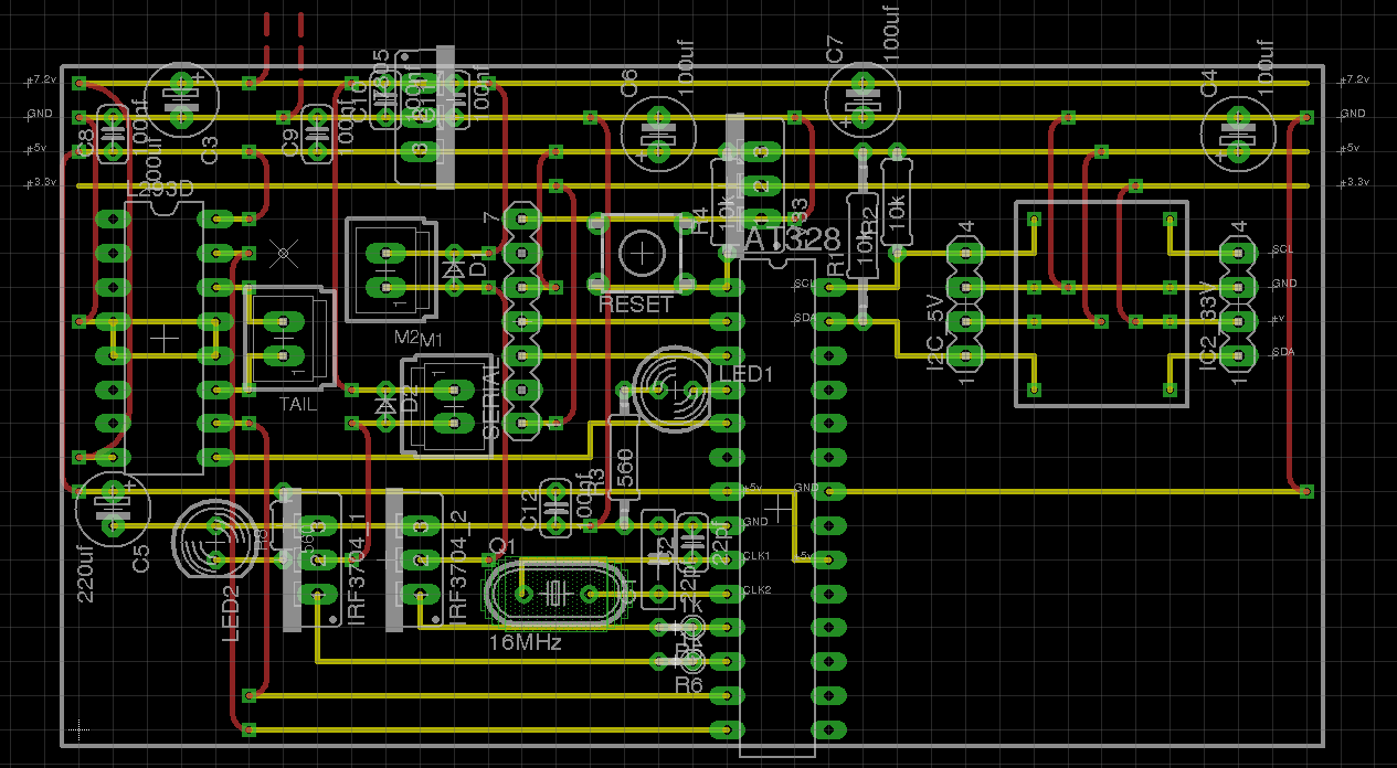
After a couple of attempts I've designed a drop in replacement board (although mine is much larger than the stock one) that can just be plugged into the existing motor and battery connectors.
Via two PWM pins connected to a couple of IRL3704 MOSFET's I can control the two main rotor blades, which when used together can adjust the height (by increasing/decreasing the speed of both motors) and provide left or right rotation (when one rotors's speed in increased and the other decreased).
Using two digital pins connected to the input lines on an L293D motor driver, the tail rotor can be made to move in either direction, tilting the main rotors and making it move forwards/backwards. An increase in speed of the main rotors is required to maintain level flight. PWM on a third pin connected to the L293D enable line can control the tail rotor's speed.
The 7.2v supply from the battery is converted both to 3.3v and 5v via an LV33 and 7805 respectively. The 5v supply is used by most of the components including the arduino, L293D (excluding the motor supply which is 7.2v), serial and i2c. The 3.3v also used for i2c after the SDA/SCL level has been converted using a sparkfun level converter. A 3.3v pin is also broken out next to the standard 6 pin serial so that a btm182 bluetooth module can be used for wireless control instead of a FTDI cable - again with the levels converted.
Below is the first version, it was built organically and so is a bit of a mess. It became unworkable when I needed to add 3.3v i2c support for the accelerometer and gyroscope. (The ATmega328 should be in the left socket the L293D in the right one.)
The second version was based on the stripboard arduino but the modular design proved to be far too heavy.
This time I laid everything out using Eagle to get it as tight as possible. The space in the bottom right has been left to later include logging to SD card via the SPI bus. The gold lines are the copper tracks on the underside of the stripboard, the red lines are jumper wires on the top.
The original stock board next to version three - the motor connectors have been removed; the grey and yellow wires were attached to key points during early experiments.
Here's the board installed in the chassic of the 9053, on the left you can see the btm182 bluetooth module.
With the board complete I can now use blueterm to perform basic remote control from my phone.
After a long wait, I've finally added a eagle schematic to the following pages:
So my stripboard arduino clone can do something useful I've built some shields for it. This one is a dual function board handling i2c (both 3.3 & 5 volt) and access to a microSD card via the SPI bus.
The i2c bus is physically accessed by the pins at the bottom of the picture above. On the left is the 5 volt pins (the 4x4 block) and on the right is the 3.3 volt ones (I've run out of pin headers so only one column is populated). Each column on both sides provides v+, SDA, SCL and ground.
The red sub-board is a sparkfun logic level converter that handles the conversion for the 3.3 volt part of the i2c bus. Unlike i2c, the lines on the SPI bus are unidirectional so I could use voltage dividers to perform the level conversion instead of the larger footprint sparkfun board.
I've used an old SD to microSD adapter as a card socket which was easy to work with as the contact spacing is the same as standard pin headers (see the top of the first picture).
The underside of the board is a bit less neat than I would like although I'm quite pleased with how the vertical solder tracks for the SD card came out.
Right now I'm using the 5v i2c bus to read from an SRF08 ranger mounted on the bottom of my prototype UAV, and the SD card to dump the values of the sensors and internal state of relevant program parameters for post test analysis. I'm going to use the 3.3v i2c bus to read from the bma180 and itg3200 once I've mounted both of them on to the UAV chassis.
Arduino code here.
04/Sep/11 - Updated with eagle schematic below - yellow horizontal lines are the copper tracks on the underside of the stripboard, red lines are jumper wires on the top.
I needed a small arduino for a UAV project, I could of just bought a mini but I wanted to see how small and cheap I could actually build one without requiring etching equipment. The final size of the board got down to 45 x 25 mm although by using a resonator instead of a crystal + two capacitors it may be possible to make it slightly thinner.
The board includes only the bare minimal - just regulated power (both 5v and 3.3v), the Atmel 328, the crystal and four capacitors (two for the power lines and two for the crystal).
On the underside you can see where the tracks have been cut. The power section is a bit of a mess as the first attempt had the regulators mounted vertically but the layout was too tight and had to changed. Even then I still had a problem when I first powered it up because the heat sinks were touching - the sink on the 7805 is grounded but the one on the LD33 is +3.3v.
The first 'shield' I made has the basic extra features - a reset button, a general purpose LED and a serial programming header compatible with the standard FTDI cable or breakout board. This board is not required in normal use and only really needs to be installed during programming.
And the underside - the pin on the right hand side does nothing electrically and is just there to help hold the shield.
The programming shield needs to be at the top of the stack as it only has eight of the stackable headers mounted on it. The main board has a full set of them and so can be anywhere in the stack, not necessarily at the bottom.
The two pins near the power capacitors on the main board are power in - I'm using a standard 9v battery but anything above 7v should work.
I've also built two more shields - one handles the interface to the UAV hardware and the other deals with the I2C bus (both 5v and 3.3v) and SD card via SPI. I'll document these in a future post.
04/Sep/11 - Updated with eagle schematic below - yellow horizontal lines are the copper tracks on the underside of the stripboard, red lines are jumper wires on the top. Notice on the photos the orientation of the 7805 and the LD33.
Below is a picture of the weathoscope mounted on the inside of the shed. You can see the USB cable on the right and the black/yellow cable of the temperature probe on the left. The probe cable runs out through the gap beween the wall and the roof, the probe itself hanging in the air.
I'm hoping that hanging there will be both out of direct sunlight and out of the rain.
Weathoscope can be found here.
Code available on github.
I've just pushed the latest server side code changes up to github. The biggest change is that the persistent storage has been moved to a postgres database instance to allow efficient retrieval based on date ranges. The database schema is just one table with two columns - a timestamp and the temperature.
The background perl script - weathoscope_logger_db.pl - now uses the DBI perl module and simply inserts the values into the database as they are read from the arduino.
On the web front end, the php script - index.php - runs a small SQL query to extract the latest captured temperature :
SELECT temp FROM log ORDER BY ts DESC LIMIT 1
It also outputs a couple of image tags linking to a third php script - temp_chart_db.php - which handles the dirty job of taking the data returned from the DB and formatting it into something the google charts api can work with. It can take an optional parameter that changes the date range from 1 day to 1 week. I plan to make longer ranged graphs available as soon as I have the data (within the bounds of reasonable query response times anyway).
There been some strange spikes on the graphs over the past week - I suspect the probe need repositioning further away from the house and the on-device smoothing probably needs it's number of samples increasing.
Weathoscope (with graphs) can be found here.
Code available on github.
Here's the first version of the weathoscope. This initial version only supports temperature but I'll add sensors as they and time become available. It's now installed in the shed with the LM335Z sticking outside sampling the air in the back garden.
And with the lid on:
The code running on it (below) dumps the current values of the sensors on a single line consisting of key/value pairs, to the serial port every 60 seconds.
#include "stdlib.h"
#include "math.h"
#include "wiring.h"
#include "WProgram.h"
#include "Wire.h"

#include <Smoothing.h>
#include <Timer.h>

//status LED
const int LEDPIN = 13;

//rotorary encoder photocell - wind speed
/* NOT USED
const int PHOTOPIN = 0;
volatile int state = LOW;
volatile int counter = 0;
*/

//LM335Z - temperature
const int LM335RATE = 1000; // 1 second
const int LM335PIN = 0;
Timer LM335Timer;
Smoothed LM335Smooth;
int LM335toDegreesC(int raw, int fudge){
//Algorithm to convert the LM335 output signal from the ADC to degrees C.
  return (((raw * 500L) / 1023L) - 273L) + fudge;
}

//dump data timer
Timer dumpTimer;
const int DUMPRATE = 60000; //60 seconds

void setup(){
  Serial.begin(9600);
  Serial.println("setup");

  digitalWrite(LEDPIN, LOW);

  /* NOT USED
  pinMode(PHOTOPIN, INPUT);
  attachInterrupt(PHOTOPIN, windSpeedISR, FALLING);
  */

  newSmoothed(&LM335Smooth, 10);
  newTimer(&LM335Timer, LM335RATE);

  newTimer(&dumpTimer, DUMPRATE);

  delay(1000);
}

void windSpeedISR()
{
  /*
  state = !state;
  counter++;
  */
}

int smoothedLM335 = 0;

void loop(){
  if( checkTimer(&LM335Timer) ){
    int rawLM335 = analogRead(LM335PIN);
    smoothedLM335 = smoothReading(&LM335Smooth, rawLM335);
  }

  if( checkTimer(&dumpTimer) ){
    digitalWrite(LEDPIN, HIGH);

    int degreesC = LM335toDegreesC(smoothedLM335, -4);

    Serial.print("degreesC:");
    Serial.print(degreesC);

    Serial.print('/'); // divider

    Serial.println();

    digitalWrite(LEDPIN, LOW);
  }

}
On the web server a perl script reads the line from the USB serial port and writes out two files. First it writes the latest line to weathoscope.out - this file can then be easily picked up by a PHP script for displaying the live data. Secondly it parses it into it's key/value pairs building a simple CSV line to be appended to weathoscope.csv. The CSV file can later be used for historical analysis and graphing. Both these files are available on the public part of the web server for potential re-use.
#!/usr/bin/perl

use Device::SerialPort;
use DateTime;
use Data::Dumper;

$LOGDIR    = "/var/www/htdocs";
#$LOGDIR    = "/tmp";
$LOGFILE   = "weathoscope.out";
$CSVFILE   = "weathoscope.csv";
$PORT      = "/dev/ttyU0";
#$PORT      = "/dev/ttyUSB1";

my $port = Device::SerialPort->new($PORT);
$port->databits(8);
$port->baudrate(9600);
$port->parity("none");
$port->stopbits(1);

open(LOG,">${LOGDIR}/${LOGFILE}") || die "can't open log file\n";
open(CSV,">>${LOGDIR}/${CSVFILE}") || die "can't open csv file\n";

while (1) {
  my $data = $port->lookfor();
  if ($data) {
    #print "$data\n";

    #write latest to LOG
    truncate(LOG, 0);
    seek(LOG, 0, 0);
    syswrite LOG, $data;

    #now decode for the CSV
    my $dt = DateTime->now();

    #looking for these
    my $degreesC = "";

    $data =~ s/\r|\n//g;

    my @keyvals = split(/\//, $data);
    foreach(@keyvals){
      my @keyval = split(/:/, $_);
      #degreesC
      if(@keyval[0] =~ /degreesC/){
        $degreesC = @keyval[1];
      }
      #blahblah
      #if(@keyval[0] =~ /blahblah/){
      #  $blahblah = @keyval[1];
      #}

    }
    #write csv
    my $csv = "$dt, $degreesC\n";
    syswrite CSV, $csv;
  } else {
    sleep(1);
  }
}
The lines outputed from the arduino are in the following format, which you can see just need to be split by a forward slash to get an array of key/value pairs and then each of these to be split by a colon to get the key and value.
key1:value1/key2:value2/key3:value3
The nicely presented data can be found here. The PHP script opens the .out file and double-splits the line, parsing the value(s) it needs. It outputs a 'standard' sodnpoo.com blog XML file that automatically gets transformed and styled.
<?php header('Content-Type: text/xml'); ?>
<?xml version="1.0" encoding="UTF-8"?>
<?xml-stylesheet type="text/xsl" href="/sodnpoo.xsl"?>
<xml>
<post>
  <title>weathoscope</title>
  <date></date>
  <p>
  <span class="header">Current temperature:
  <?php
    $out = file_get_contents("/htdocs/weathoscope.out");
    $keyvals = explode('/', $out);
    foreach($keyvals as $keyval){
      //echo $keyval."\n";
      $kv = explode(':', $keyval);
      if($kv[0] == 'degreesC'){
        echo $kv[1];
      }
    }
  ?>
  </span></p>
  <p>
  <a href="/weathoscope.csv">log file (csv)</a>
  </p>
</post>
</xml>
I'm planning on adding a humidity sensor and my homemade wind speed meter next. Although I have plans for a laser rainfall meter and barometer eventually.
Code available on github.
I wanted to be able to use my Futaba RC transmitter/receiver as a manual override system for various arduino projects. After some googling I couldn't find any code to read more than 3 channels, some implementations using pulseIn() but suffering because of the inherent time-out. I also found Reading servo PWM with an Arduino which fed the PWM from the RC receiver into one of the interrupt pins. This looked like the right way to do it although this means that each channel needs it's own pin, limiting it's use to two channels on a 328 based arduino. It looks like you can get all channels on one line if you modify the receiver to gain access to the PPM line but I wanted to avoid that if possible.
The code uses the timer interrupt available in the playground. I'm using Timer3 as it's written for the Mega1280 which is what I use for development. I believe but I haven't tested yet, that Timer1 should be pretty much a drop in replacement with only the #include and the initialize() and attachInterrupt() lines in setup() needing some minor changes.
The amount of code executed in callback() will affect how small of an interval you can use on the timer - too small and the arduino spends most of it's time servicing the interrupt slowing down the code in loop() - but the larger you go the worse the pulse width resolution is. To minimise the possible useful interval value I've attempted to optimise callback() including using direct PIN I/O using rawDigitalRead() instead of the standard digitalRead() - this is Mega1280 specific mapping and would either need to be re-written for a 328 or the slower digitalRead() used instead. As it's an 8 bit processor changing variable types from int to byte made a significant difference.
Using the simple demo program below I can read 5 channels with a interval/resolution of 40 microseconds - 4 takes 32, 3 takes 26, 2 takes 14 and 1 takes 10 microseconds. These values are the lowest while keeping a single iteration of loop() to ~50 milliseconds. This might not be enough resolution for all cases but should be enough for my uses.
#include <TimerThree.h>

const byte SERVOPIN = 3;
const byte SERVOPIN1 = 4;
const byte SERVOPIN2 = 5;
const byte SERVOPIN3 = 6;
const byte SERVOPIN4 = 7;

const byte MAXRCPWMS = 5;
const byte RCPINS[MAXRCPWMS] = {
  SERVOPIN,
  SERVOPIN1,
  SERVOPIN2,
  SERVOPIN3,
  SERVOPIN4, /**/
};

  /* < 50 millis for loop()
  1 = 10
  2 = 14
  3 = 26
  4 = 32
  5 = 40
  */
const byte RCSAMPLERATE = 40; //in microseconds

struct tRcPwm {
  unsigned long lastMicros;
  byte pin, lastState;
  int pulseWidth;
};

volatile tRcPwm rcPwm[MAXRCPWMS];

void setup(){
  Serial.begin(9600);

  for(int i=0;i<MAXRCPWMS;i++){
    rcPwm[i].pulseWidth = 0;
    rcPwm[i].lastMicros = 0;
    rcPwm[i].lastState = 0;
    rcPwm[i].pin = RCPINS[i];
  }

  pinMode(10, OUTPUT);
  Timer3.initialize( RCSAMPLERATE );
  Timer3.attachInterrupt(callback);
}

void loop(){
  Serial.print(millis());

  for(int i=0;i<MAXRCPWMS;i++){
    Serial.print(" ");
    Serial.print(i);
    Serial.print(": ");
    Serial.print(rcPwm[i].pulseWidth);
  }

  Serial.println();
}

byte rawDigitalRead(byte pinnum){
  switch(pinnum){
    case 3:
      return !((PINE & (1<<5))==0); // 3
    case 4:
      return !((PING & (1<<5))==0); // 4
    case 5:
      return !((PINE & (1<<3))==0); // 5
    case 6:
      return !((PINH & (1<<3))==0); // 6
    case 7:
      return !((PINH & (1<<4))==0); // 7
  }
}

void callback(){
  for(byte i=0;i<MAXRCPWMS;i++){
    //byte state = digitalRead(rcPwm[i].pin);
    byte state = rawDigitalRead(rcPwm[i].pin);

    if( rcPwm[i].lastState != state ){
      unsigned long now = micros();
      if( state==HIGH ){ //rising
        rcPwm[i].lastMicros = now;
      }else{ //falling
        rcPwm[i].pulseWidth = now - rcPwm[i].lastMicros;
      }
      rcPwm[i].lastState = state;
    }
  }
}
Latest code available on github.
Here's a couple of pics of my Mega connected to both the bma180 and itg3200 that Santa brought for me.
On the left is a logic level converter with the bma180 in the middle and the itg3200 on the right.
Here's a close up of just the bma180 and the itg3200.
Example code can be found on github. itg3200_demo.pde and bma180_demo.pde.
Thanks to Fabio Varesano for the itg3200 code and m.ryandesign for the bma180 code.
Wind speed
To measure wind speed I needed to be able to count the rotations of some sort of propeller in a given time period. This is the device I came up with to measure the rotations:
The device uses an infrared LED and photocell taken from a broken PS2 ball mouse. The output from the photocell is connected to an arduino interrupt pin.
The vertical axle and cog are taken from a broken small toy helicopter. The bottom of the cog has been covered with black tape except for a single window that exposes the photocell to the IR from the LED once per rotation.
Below is a close up where you can see the clear LED at the bottom, the black photocell at the top and the window in the cog.
I still need to make the propeller - which will most likely be two cups on the end of short arms connected to the axle head - and to acquire a suitable housing for it that can be easily mounted.
Example code can be found here : weatherstation.pde.
Temperature
I've started building an arduino powered weather monitoring station. The plan is to have sensors for the various different aspects (wind speed, temperature etc) so I can publish the live data and keep a log that can be used for later analysis.
For temperature measurement I'm using the LM335Z which can cover a range of -40 to +100 degrees centigrade. It needs one analog pin which after some conversion gives you the temperature in Kelvin.
Below you can see I'm only using two of the 335's legs - v+ and v-. V+ is pulled high on one side via a 1K resistor and on the other is connected to an arduino analog pin. V- is connected to ground.
I use the function below where raw is the raw value returned from analogRead() and fudge is how much to offset the result by after calibration. (I used ice in a bag.) The '-273' is there to convert from Kelvin to degrees centigrade.
  int LM335toDegreesC(int raw, int fudge){
    return (((raw * 500L) / 1023L) - 273L) + fudge;
  }
Example code can be found here : weatherstation.pde.
I've just pushed my arduino projects folder on to github - https://github.com/sodnpoo/arduino